Pinning down possibilities for pump problems

Problems in pumping systems can, seemingly logically, be blamed on the pump. There could however be other hidden issues; ambient conditions can affect pumpage, or perhaps there are problems in the system itself. In this article we discuss a systematic approach to help determine where the problem really lies.
When a newly repaired pump performs poorly, it seems logical that something is wrong with it. While that might be true, good troubleshooting procedures should also eliminate several other possibilities, including problems with the fluid being pumped (the pumpage), or with the pipes, fittings and vessels that are connected to the pump (the system). Fortunately, a savvy technician with just a basic understanding of pump curves and performance parameters can quickly narrow down the possibilities–especially those associated with the pump.
Pump curves
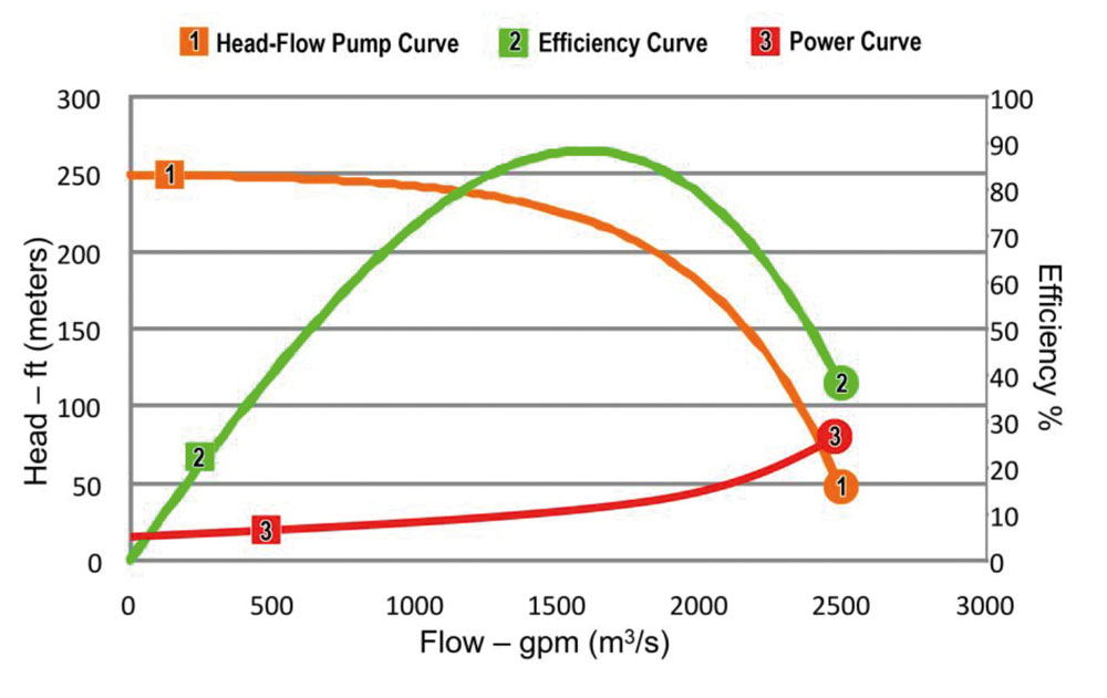
This discussion is limited to the most common pumps in industrial and commercial applications– centrifugal pumps. The performance curves in Figure 1 illustrate how the parameters of head, flow rate, efficiency and power relate to one another for a typical centrifugal pump. Note that as head increases, flow decreases, and vice versa (Head-Flow Pump Curve, Figure 1).
For any certain flow rate, there is a corresponding amount of head. The impeller design dictates a specific flow rate at which the pump will perform most efficiently–i.e., its Best Efficiency Point
Many pump problems, and some system problems, will cause the pump to operate at a point below its normal pump curve line.
(BEP). Many pump problems, and some system problems, will cause the pump to operate at a point below its normal pump curve line. A technician who understands this relationship can measure the pump parameters and isolate the problem to the pump, the pumpage, or the system.
Is it the pump?
To determine if the problem is the pump, the Total Dynamic Head (TDH) and flow should be measured at the pump and compared to the pump curve for that pump (see sidebar on page 49). The TDH is the difference between discharge and suction pressure, converted to feet or meters of head. (Caution: If there is little or no head or flow on start-up, the pump should immediately be shut off to verify that there is sufficient fluid in it–i.e., that the pump is primed. Running a pump dry may damage the seal.)
• If the operating point is on the pump curve, the pump is operating properly. Therefore, the problem is with the system or possibly the pumpage.
• If the operating point is below the pump curve, the problem could be the pump, the system, or possibly the pumpage.
Is it the pumpage?
Ambient conditions like temperature can change the viscosity of the pumpage, which in turn may change the head, flow and efficiency of the pump. Mineral-based oil is a good example of a liquid that changes viscosity with temperature. When the pumpage is a strong acid or base, dilution can change its specific gravity, which may affect the power curve.
To find out if the pumpage is the problem, its properties need to be verified. Tests for viscosity, specific gravity and temperature of the fluid are readily available and inexpensive. Standard conversion charts and formulas from the Hydraulics Institute and elsewhere can then be used to determine if the pumpage is adversely affecting the pump’s performance.
Is it the system?
Assuming the fluid properties have been ruled out, the problem must be with the pump or the system. Again, if the pump is operating on the pump curve, it is working properly. In that case, the problem must be the system to which the pump is connected.
There are two possibilities here. Either the flow is too low (and therefore the head is too high), or the head is too low (indicating the flow is too high). When considering head and flow, remember that the pump is operating on its curve. Therefore, if one is too low, the other must be too high.
Low flow (head too high). A low flow condition usually indicates a restricted line. If the restriction is in the suction line, there will likely be cavitation; otherwise, it is probably in the discharge line.
Other possibilities are that the suction static head is too low, or that the discharge static head is too high. For example, a suction tank may have a float switch that fails to shut off the pump when the fluid level drops below the set point. Similarly, a discharge tank may have a “high level” switch that has malfunctioned. a discharge tank may have a “high level” switch that has malfunctioned.

Low head (flow too high). A low head condition indicates too much flow. And it is likely that the flow is not going where it should. System leaks can be internal or external. A diverter valve that allows too much flow to bypass, or a failed check valve that lets flow circulate backwards through a parallel pump, would result in too much flow and low head. On a municipal water system with buried water mains, a major leak or line break will allow too much flow and result in low head (low line pressure).
Blockages and leaks. Looking for blockage or leaks in a hydraulic system is like looking for opens and shorts in an electrical system, except that the parameters to measure are pressure and flow rather than voltage and current. Where there is a blockage or a leak, there will be an abnormal pressure differential across the area or component involved. It is easier to locate a problem by checking pressure (THD) than by measuring flow (see sidebar).
Other system problems. Even if the pump is not operating on its curve, there are some system problems that must be ruled out before the pump can be identified as the culprit. For example, if vapor is getting into the pump by air entrainment or cavitation, the pump will not operate on its curve, even if there is nothing wrong with it. Performing vibration analysis in real time while varying the pump suction will help identify cavitation and air entrainment. If the pump does not operate on its curve after these conditions have been eliminated, there is very likely a problem with the pump.
What could be wrong with the pump?
When a pump does not operate on its curve and cavitation and air entrainment have been eliminated, the most likely causes are a damaged impeller, blockage in the impeller (see Figure 3), blockage in the volute, or excessive wear ring or impeller clearance. Other causes would be related to the speed of the pump, such as the shaft spinning in the impeller, or an incorrect drive speed. While drive speed can be verified externally, investigating the other causes will involve opening the pump.
Conclusion
Troubleshooting pump performance is straight-forward. By measuring the pump’s head and flow and comparing the results to the manufacturer’s pump curve, and checking for air entrainment and cavitation, the technician can readily determine if the problem is with the pump or the system. The properties of the pumpage can also be tested to rule them out as the cause of the problem.
Measuring pump operating parameters
Often the most difficult parts of troubleshooting pump performance is measuring the pressure and flow. To determine pump TDH (i.e., the difference between the suction and discharge pressures), a suction gauge and a discharge gauge are required at both the pump suction and discharge. Pump suction pressure can be below atmosphere (a vacuum), so the suction gauges should read vacuum or pressure.
Although flow can be harder to measure than pressure, ultrasonic flow meters can accomplish the task from the outside of the pipe (Figure 2). There are several kinds that may work, depending on the type of pumpage, so it is important that the correct type is selected, and that it is installed and calibrated properly.
Another way to determine flow is a method which works well on pumps that draw from an open sump. Simply measure the change in depth of the liquid during a short interval (15–60 seconds) with all other flows into and out of the sump closed. Compute the flow as the volume of the change in sump level, converted to gallons (m3) per unit time.
EASA is an international trade association of more than 1,700 firms in nearly 70 countries that sell and service electromechanical apparatus. For more information, visit www.easa.com .
Text: Gene Vogel, pump and vibration specialist at EASA
Images: EASA and SHUTTERSTOCK


Subscribe to the free Maintworld newsletter here!
Finnish engineers create novel sensor technology to prevent hot car deaths
Finnish engineers have developed a sensor-based system that can help save tens of thousands of children – and even pets – locked up in cars, intentionally or accidentally, from heat-related deaths each year. The new PictM™ technology is a solution to calls from US and European safety regulators’ that new rules be implemented mandating child presence detection (CPD) systems in new cars. This will help avoid senseless heat-stroke deaths of unattended children.
A CPD system is a device that detects the presence of a child or pet left behind in the car and sends an alert to the mobile phone of an adult responsible when the driver leaves the vehicle.
With the number of new cars entering the market continuously rising, studies predict that such an automotive sensor market will be worth tens of billions of dollars by 2030, growing at around 10% per year.
Tragically, on average, there are 38 hot car child deaths per year in the United States alone. That is 942 preventable tragedies since 1998. Thus, such technology is highly needed.
– Our PictM sensor technology is anticipated to revolutionize the automotive optical sensing market by bringing a 3D gauge available to car makers for in-cabin and for car surroundings that can measure objects up to tens of meters in the distance.
This in turn offers a dimensionally accurate model of the environment with millimeter accuracy and without distortion, describes Uula Kantojärvi, Director at Finland’s Espoo-based PiBond Oy.
According to Kantojärvi, the PictM technology adds micrometer-scale movement to each 3D point detected by a camera.
– This happens in real-time, with a latency of a few milliseconds, producing up to 200,000 3D-measurement points per second, Kantojärvi explains.

According to Kantojärvi, the system can detect a child’s breathing in a vehicle. The technology illuminates the target with a laser dot pattern and detects any signal variation seen with the camera. Thus, it can distinguish living objects from luggage and other inanimate objects inside the car.
Growing demand for new car safety features
The number of sensors attached to cars is growing as manufacturers introduce new safety features. Many car manufacturers are developing autonomous vehicles that need accurate situational awareness of the car’s environment and the people inside.
Starting from 2023, if a car manufacturer wishes to get a five-star rating for its new car model from Euro NCAP, it must include the CPD system as standard. This is stated in the new protocol developed by Euro NCAP (European New Car Assessment Program) that assesses the safety of new cars.
– In many countries, there is, or will be legislation to require new cars to have a method to warn the driver if they forget a child in the back seat. We believe that the PictM sensor will add value with more accurate detection, Kantojärvi notes.
– This technology could potentially end up on the automotive market when we can do this in collaboration with major automotive sensor suppliers, he continues.
At what stage is the development of such CPD technology – when could we start seeing PictM sensors installed in new cars?
– The development work has progressed to the first compact instrument that will be used for various application trials and the gathering of customer needs. At the same time, we are designing other next-generation devices and solutions to meet the identified industry needs.
Development work continues in Finland, Kantojärvi stresses.
– We have received support from both Business Finland and the European Union. We also have received assistance from Finnish small- and medium-sized enterprises, research institutes, and universities. Finland has a lot of expertise in the development of complex optical devices.
MANY APPLICATION AREAS – INCLUDING INDUSTRIAL MAINTENANCE
Uula Kantojärvi adds that an intriguing future possibility for the new technology is to have a measuring device that can also detect a living object while the car is moving. Currently, this is a major technological challenge, he admits.

The main markets for such technology are in developed countries with legislation for this type of security application. According to Kantojärvi, the potential customers for such an application are sensor suppliers to the automotive industry. However, other industries could benefit from such technology – including the industrial maintenance sector. These include autonomous robots, industrial precision surface measurements with displacement data, human physiology measurements, and 3D modelling of faces and bodies.
– We see many application areas where the PictM sensor adds value to its user by providing an accurate 3D model of the surroundings and a vibration map. This example, where we measured a child’s breathing in the back seat, is an excellent example of what PictM is capable of.
– The future for such technology looks bright because there are many applications where the real environment around us needs to be digitized in a reliable 3D as many applications are moving to the virtual world. We are currently looking for partners in different application areas, Kantojärvi concludes.
Text: Nina Garlo-Melkas Images: PiBond
Subscribe to the free Maintworld newsletter here!
Maintaining the Future: Industry 5.0 Triumphs Over Industry 4.0’s Challenges
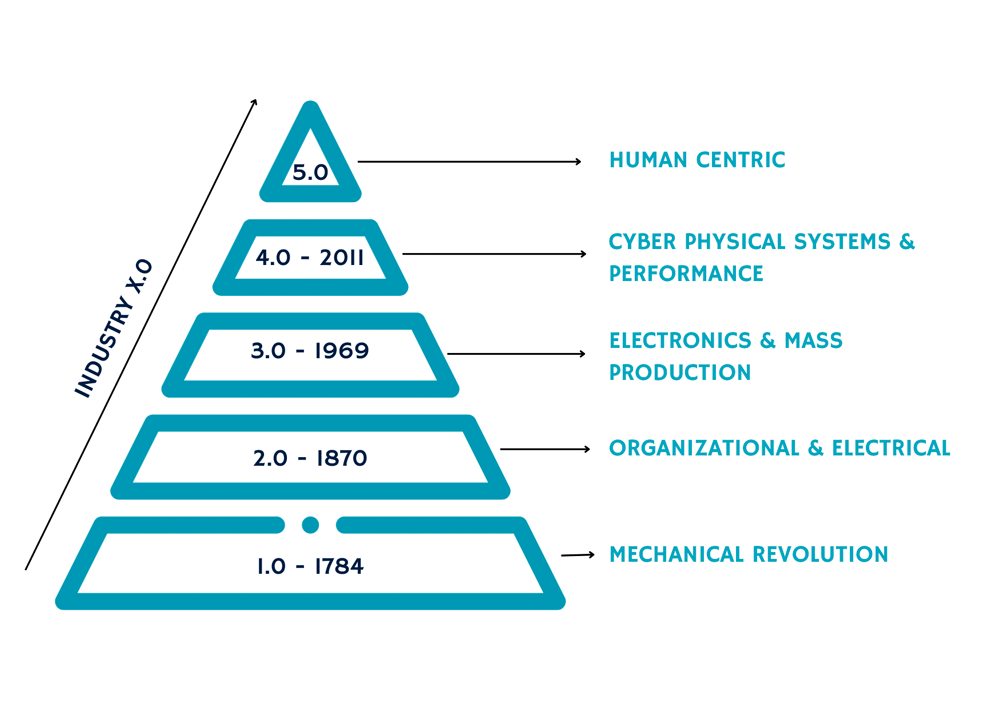
The Concept of Industry 5.0
The concept of Industry 4.0, while initially promising, encountered various challenges and limitations that ultimately led to its partial failure. Despite its emphasis on automation, data exchange, and manufacturing technologies, it often overlooked the human element, neglecting the crucial role of workers in the production process. Concerns also arose about its environmental sustainability and societal impact, highlighting the need for a more holistic approach to industrial development.
The emerging concept of Industry 5.0 represents a significant departure from traditional industrial models, emphasizing a holistic approach to production that prioritizes human-centricity, sustainability, and resilience. While the exact implications and disruptions of Industry 5.0 remain uncertain, recognition of its potential to bridge the gap between the physical and virtual worlds is growing. In this context, Industry 5.0 embodies a broader purpose that extends beyond profit generation. It underscores the need for industrial practices to align with societal and environmental considerations, emphasizing responsible innovation that benefits all stakeholders, including investors, workers, consumers, and the environment.
A key facet of Industry 5.0 is its human-centric approach, which places human needs and interests at the forefront of the production process. This approach leverages technology to accommodate the requirements of workers, ensuring their well-being and fundamental rights are upheld. Sustainability is another critical tenet, necessitating the implementation of circular processes and resource-efficient technologies to reduce waste and environmental impact. Resilience also plays a vital role in Industry 5.0, advocating for the development of robust industrial systems that can withstand disruptions and support critical infrastructure, particularly in times of crisis. The concept promotes the establishment of adaptable production capacities and flexible business processes, fostering a resilient and crisis-ready industrial landscape.
Ultimately, Industry 5.0 is defined by its commitment to societal goals, prioritizing the well-being of industry workers and ensuring environmentally sustainable production practices that align with the planet’s natural boundaries. The transition to Industry 5.0 promises a wealth of benefits not only for companies but also for workers. Benefits span the spectrum from enhanced talent attraction and retention to improved energy efficiency and heightened overall resilience.
There are some possible dangers inherent to the shift. Industry needs to ensure sustained competitiveness and relevance by adapting to evolving global markets and societal shifts. While there might be a short-term risk of temporarily losing competitiveness to those not yet embracing Industry 5.0, strategic timing and coordinated investments can help mitigate this potential setback. The most significant peril is the failure to engage with the broader societal transition towards sustainability, human-centricity, and resilience, risking competitiveness in the long run.
Human-Centric
Industry 5.0 represents a paradigm shift that addresses the concerns and challenges associated with the concept of the ‘dark factory’, one where humans are not needed. By prioritizing the human-centric approach, Industry 5.0 integrates advanced technologies to enhance the capabilities and well-being of workers, thereby dispelling the notion of a dark, automated workplace devoid of human presence. This shift towards Industry 5.0 represents a profound transformation in perspective, with a notable shift from a technology-driven to a human-centric approach. This necessitates the incorporation of societal constraints, ensuring no one is left behind. Consequently, the industrial sector must establish a secure and empowering work environment, respect human rights, and develop specific skill sets for workers.
Withing the framework of Industry 5.0, the industry worker assumes a significantly elevated position, viewed not as an expense but as an investment in the company’s growth. This reorientation necessitates a commitment to the advancement of employee skills, capabilities, and well-being, signalling a departure from the traditional practice of balancing worker costs with financial revenues. Moreover, it underscores the critical role of technology in serving the diverse needs of industry workers, empowering them and fostering an inclusive work environment. Addressing workplace safety and inclusivity, Industry 5.0 leverages advancements in robotics and AI to mitigate physical risks and streamline complex tasks, thereby reducing workplace accidents. Technologies like AI, virtual and augmented reality, and wearables also contribute to safeguarding workers’ mental health, emphasizing the importance of maintaining a balance between work and well-being.
A key area where Industry 5.0 yields significant benefits is in attracting and retaining skilled talent. Given the challenges of filling positions that demand digital and multi-disciplinary skills, the focus on accommodating the preferences and values of the millennial workforce is crucial. Research has found the millennial generation is more inclined towards socially responsible and environmentally conscious companies, prioritizing workplace environments that align with their values and offer a sense of purpose. Companies need to adapt their practices, fostering a culture of social responsibility and sustainability to remain competitive in the hiring market.
Sustainability
The 5.0 concept involves leveraging innovative green technologies, driven not only by environmental concerns but also by the potential for enhanced corporate image and cost savings on energy and materials. While industrial production often demands more energy and contributes to increased carbon emissions, innovations and smarter production planning can reverse this trend. Despite notable improvements in energy efficiency across various sectors, the pace of progress in energy-intensive industries has recently slowed, necessitating more targeted research and innovation efforts in this domain.
Resilience
Industry 5.0 champions increased resilience in the face of disruptive changes, both geopolitical and environmental. By fostering adaptive strategies at various levels of value chains and industrial systems, industry players can manage vulnerabilities and minimize the impacts of unforeseen circumstances. Leveraging digital technologies, such as real-time risk monitoring and cybersecurity measures, can bolster industry resilience, ensuring smooth operations even in the face of technical disruptions and cyber threats. The emphasis on resilience is growing, particularly in light of the disruptions caused by the pandemic and the intensifying frequency of extreme weather events attributed to climate change.

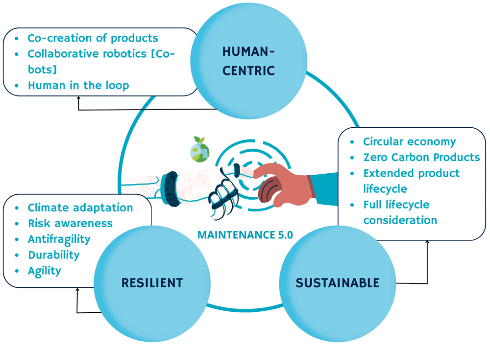
Maintenance 5.0
The shift from Maintenance 4.0 to Maintenance 5.0 mirrors the broader transition occurring in the industrial landscape. Maintenance 4.0 focuses on the integration of digital technologies, such as the Internet of Things (IoT), data analytics, and predictive maintenance, to optimize industrial maintenance processes. It emphasizes the use of advanced data-driven techniques and automation to enhance equipment reliability and reduce downtime. Maintenance 5.0 takes this a step farther by incorporating a more human-centric approach, aligning with the principles of Industry 5.0. Maintenance 5.0 also prioritizes sustainability and resilience in maintenance operations. This shift is critical in the face of the dual challenges posed by the COVID-19 pandemic and the escalating impact of climate change. As Maintenance 5.0 increasingly aligns with sustainable and resilient principles, it will become a cornerstone for ensuring the long-term viability and adaptability of industrial processes, mitigating the adverse impacts of global crises on operational efficiency and overall productivity.
Human-Centric Orientation
Maintenance 5.0 goes beyond the traditional focus on machines and processes to prioritize the well-being and involvement of maintenance workers. This approach acknowledges the critical role of human expertise in maintaining industrial systems and promotes the integration of workers into the digitalized maintenance ecosystem. It aims to empower workers through the use of innovative technologies, offering them opportunities for skill development, greater autonomy, and involvement in the decision-making process. It also ensures a safe and inclusive work environment, utilizing technologies to mitigate workplace risks and prioritize workers’ physical and mental well-being.
Maintenance 5.0 emphasizes the adoption of eco-friendly practices to reduce the environmental footprint of industrial processes.
Sustainability
Maintenance 5.0, as an evolution of the maintenance paradigm, emphasizes the integration of sustainability principles within its framework. It recognizes that maintenance practices play a vital role in achieving sustainable development goals, aligning with the broader efforts to minimize environmental impact, conserve resources, and promote social well-being. The concept of sustainability within Maintenance 5.0 underscores the adoption of sustainable practices, such as resource-efficient maintenance processes and circular economy principles, to optimize resource utilization and minimize environmental impact. By implementing predictive and preventive maintenance strategies, industries can reduce unnecessary waste and conserve energy, thereby contributing to the global efforts towards sustainable development.
The sustainability dimension of Maintenance 5.0 encompasses the following key aspects:
• Environmental impact reduction: Maintenance 5.0 emphasizes the adoption of eco-friendly practices to reduce the environmental footprint of industrial processes. This includes the efficient use of resources, waste reduction, and the implementation of sustainable technologies that contribute to a circular economy.
• Energy efficiency: Sustainable maintenance practices focus on optimizing energy consumption and minimizing the carbon footprint of industrial operations. This involves the use of energy-efficient technologies, the adoption of renewable energy sources, and the implementation of energy management systems to reduce overall energy consumption.
• Lifecycle management: Maintenance 5.0 promotes the concept of lifecycle management, which involves considering the entire lifecycle of assets and equipment. This approach integrates sustainable practices throughout the asset lifecycle, from design and production to operation, maintenance, and eventual decommissioning or recycling.
• Circular economy integration: Maintenance 5.0 actively supports the integration of circular economy principles within industrial maintenance processes. This involves extending the life of assets through effective maintenance, refurbishment, and reuse, as well as promoting the recycling and repurposing of materials and components to minimize waste and resource depletion.
By incorporating these sustainability dimensions, Maintenance 5.0 not only enhances operational efficiency and asset performance but also contributes to the overall sustainability goals of organizations, aligning with global efforts to promote environmentally responsible and socially conscious industrial practices.
Resilience
There is a clear need for resilient maintenance strategies that can swiftly adapt to changing circumstances and address disruptions in the industrial landscape, thus ensuring the continuous and reliable operation of critical infrastructure, even during unforeseen crises. Simply stated, resilience in Maintenance 5.0 refers to the ability of industrial organizations to anticipate, adapt to, and recover from various disruptions and challenges that may arise within their operational environment. It emphasizes the implementation of proactive strategies and advanced technologies to ensure the continuous and efficient functioning of critical assets, even in the face of unexpected events or adverse conditions. Resilience is crucial to maintain operational stability, minimize downtime, and sustain productivity, thereby enabling organizations to remain competitive and sustainable in the long run.
Some key aspects related to resilience in Maintenance 5.0 are the following:
• Predictive and preventive maintenance: By integrating predictive maintenance techniques, such as condition monitoring, data analytics, and real-time asset performance tracking, organizations can proactively identify potential equipment failures or operational inefficiencies before they escalate into significant disruptions. Implementing preventive maintenance protocols based on predictive insights allows companies to address issues early, minimizing the risk of costly downtime and ensuring the uninterrupted operation of critical assets.
• Risk management and contingency planning: Effective risk management is a fundamental component of resilient maintenance practices. Organizations need to identify potential vulnerabilities within their operational processes and develop comprehensive contingency plans to mitigate the impact of unforeseen events, such as natural disasters, supply chain disruptions, or technological failures. By establishing robust risk assessment frameworks and implementing adaptive strategies, companies can enhance their ability to respond to and recover from various operational challenges while maintaining overall system resilience.
• Data-driven decision-making: By leveraging advanced data analytics and intelligent automation, Maintenance 5.0 enables organizations to make informed and data-driven decisions regarding asset management and maintenance strategies. By harnessing the power of Big Data and AI-driven insights, companies can optimize maintenance schedules, streamline repair processes, and prioritize resource allocation, thereby enhancing the overall resilience of their maintenance operations. Data-driven decision-making empowers organizations to respond swiftly to changing operational conditions and proactively address emerging maintenance needs.
• Adaptive and flexible maintenance processes: Resilience in Maintenance 5.0 emphasizes the development of adaptive and flexible maintenance processes that can accommodate evolving operational requirements and changing environmental conditions. By fostering a culture of continuous improvement and agility, organizations can optimize their maintenance strategies in response to dynamic market demands, technological advancements, and regulatory changes. Implementing agile maintenance methodologies enables companies to swiftly adapt to new challenges and opportunities, ensuring the efficient and sustainable operation of their assets.
• Technology integration for enhanced resilience: Leveraging advanced technologies, such as IoT devices, digital twins, and cloud-based monitoring systems, enables organizations to build resilient maintenance frameworks that facilitate real-time asset tracking, remote diagnostics, and predictive maintenance scheduling. Integrating smart sensors and interconnected systems within industrial facilities enhances the overall visibility and control of critical assets, enabling organizations to proactively identify potential issues and swiftly address them, thereby minimizing the risk of operational disruptions and ensuring continuous asset reliability.
By incorporating these key aspects, organizations can strengthen their resilience in Maintenance 5.0, fostering a robust operational framework capable of withstanding challenges and uncertainties while ensuring the sustainable and efficient functioning of critical assets.
Conclusion
Overall, the shift from Maintenance 4.0 to Maintenance 5.0 represents a transformational journey from data-driven and automated maintenance practices to a more holistic approach that integrates the well-being of workers, sustainability, and resilience into the core of maintenance operations. By embracing Maintenance 5.0, industries can ensure the optimal performance of their equipment and the empowerment and safety of their maintenance workforce, while contributing to a more sustainable and adaptable industrial ecosystem. In essence, the comprehensive adoption of Industry 5.0 principles in Maintenance 5.0 can pave the way for a sustainable and adaptive industrial landscape, not only providing economic benefits but also promoting environmental consciousness and societal well-being.
Text: Prof. Diego Galar / Prof. Ramin Karim / Prof. Uday Kumar Images: stockphoto, Diego Galar
Subscribe to the free Maintworld newsletter here!
Bearing Lubrication 4.0: Autonomous and Smart lubrication assisted by ultrasound

It is estimated that 60-80% of bearing failures are related to lubrication. Bearing failures very often lead to unplanned downtime, which often has a significant impact on production and related equipment. This downtime is maby times very costly. Although the costs vary according to the severity of the incident and the industry in question, they do add up to production costs.
The most frequent cause of bearing failure is directly linked to lubrication, so this is a real probme. Its impact on the reliability of industrial equipment is well established! The facts show that, for many years, the lubrication of bearings has been treated more randomly than in a methodical and controlled way.
Many technicians have resorted to ‘preventive’ lubrication based on time: lubricating at a fixed period of time without any physical measurement of the bearing in order to determine whether or not lubricating is required! Every X months, a grease gun appears in front of the bearing to be lubricated and the bearings are lubricated in this way.

Manual lubrication, based solely on the manufacturer’s lubrication interval data, gives rise to at least the following two risks:
• The risk of under-lubrication increases the mechanical constraints of rotation and can be the cause of failures leading to equipment breakdowns and stoppages, as well as costly corrective maintenance.
• The risk of over-lubrication, which has been identified by a large number of studies as the main cause of premature bearing failure.
Principle of Ultrasound technology applied in lubrication :
Ultrasonic technology uses specially designed sensors to detect and monitor the level of friction in bearings.
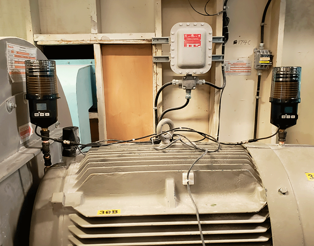
In the case of lubrication, the ultrasonic level detected by a sensor in contact with the bearing is directly linked to the friction level of the bearings. From this point onwards, the maintenance engineer responsible for lubricating bearings has two choices:
• Manual lubrication, using a simple hand-held tool to listen to the bearings during the lubrication operation;
• The installation of an autonomous, ultrasonic-assisted lubrication system to carry out this operation safely, efficiently and without human intervention.
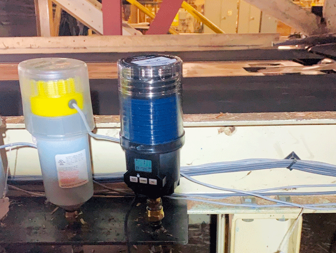
Lubrication 4.0: autonomous, ultrasound-assisted lubrication
A fully autonomous lubrication system completely replaces human intervention for lubrication operations. It is an intelligent lubrication and monitoring system, reducing bearing failures caused by poor lubrication practices by 80%.
How does it work?
Using ultrasound, this system measures bearing friction levels in real time. It enables lubrication problems and requirements to be detected at an early stage, well before the bearings are damaged.
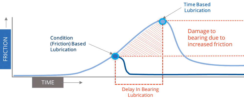
By using bearing friction as a guide, the system enables bearings that require lubrication to be precisely lubricated with the right amount of lubricant, avoiding over- and under-lubrication. As the friction level is measured continuously and in real time, even during lubrication, the system will stop lubricating on its own as soon as the friction level has dropped to its reference value.
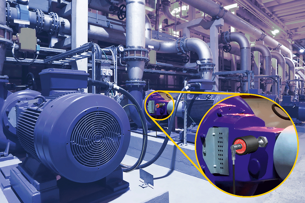
This totally autonomous system means that only the bearings that need lubrication will be lubricated, when they need it and with the right amount of lubricant.
Ultrasonic technology for intelligent lubrication offers a number of advantages:
• Know precisely when to lubricate
• Know precisely how much lubricant to apply
• Always use the right type of lubricant
• Eliminate the risk of lubricant contamination
• Reduce lubricating time and resources
The benefits of an Ultrasound Assisted Lubrication 4.0 solution
• Easy to install and use
• Multiple connection capabilities: Ethernet, Wi-Fi, 4G,5G
• Compatibility with existing systems and software
• Identify lubricating needs early on
• Lubricate as required
• Drastically improve bearing life
• Avoid over- and under-lubricating
• Reduce lubricating time
• Reduce lubricating resources
• Reduce lubricant consumption
• Reduce failure rates
Finally, it should be noted that such a solution will provide software-based, permanent, real-time monitoring of lubrication practices. For example, for the OnTrak, we have the UE Insights: a Cloud platform for storing and monitoring remote data. This fully customisable platform stores all data relating to the condition and lubrication of bearings. It can be used to create monitoring dashboards and set alarm levels. Users can choose to use pre-configured dashboards and widgets, or create their own indicators. This is a web-based platform that requires no software installation and can be consulted from any type of device connected to the internet: desktop PC, laptop, tablet, smartphone, etc.
Conclusion
From a time-based periodic lubrication perspective, it is assumed that bearings need to be lubricated at regular, fixed time intervals. The question then becomes: how can these time intervals be established? This is often a combination of manufacturer’s data, valid for general cases, or for bearings mounted on manufacturer’s test benches, and approximations based on empirical experience of the same type of equipment.
By using ultrasonic technology, lubrication technicians will be able to know which bearings to lubricate, when to lubricate them and how much lubricant to use.
These three pieces of information, especially if delivered in real time and for each bearing to be lubricated, will make it possible to considerably improve lubrication practices, reduce lubrication times and the ammount of lubricant consumed, as well as drastically reducing bearing breakdown rates.
Text: Peter Boon, Product Specialist, UE Systems Images: UE Systems
Subscribe to the free Maintworld newsletter here!
Mastering Ultrasound Monitoring with the CONMONSense Sensor Range: A Breakthrough in Asset Reliability
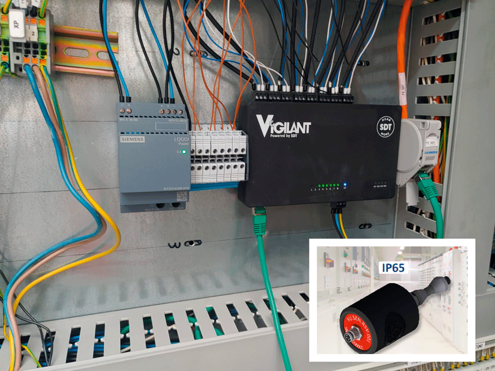
For industrial maintenance and condition monitoring practitioners, precision and reliability are paramount. The SDT CONMONSense range of sensors is a game-changing solution, opening up a new era of ultrasound monitoring. With advanced technology and unparalleled features, these sensors provide a consistent, robust, and cost-effective means of tracking the health of your critical assets.
The Power of Ultrasound in Your Hands
The CONMONSense sensors are part of the SDT Ultrasound Solutions product family, introducing a set of heterodyned ultrasound sensors with a unique capability to detect vibroacoustic phenomena in the air or through solid mediums. What sets these sensors apart is their ability to provide direct audible signals, eliminating the need for specialized SDT handheld devices with higher sampling rates. This simplifies the monitoring process, making it more efficient and readily implementable in your organization.
Embedded with analog electronics, the CONMONSense sensors perform the heterodyne process within the sensor itself. This design not only ensures compatibility with existing acquisition systems (with standard outputs) but also fine-tunes the sensor’s response, making it easier to connect and integrate into your monitoring infrastructure.

With a typical band-pass frequency range between 250 Hz to 4kHz, these sensors convert ultrasound signals into audible form, optimizing them for the human ear. The standardized analog outputs are easily interfaced with a wide range of acquisition systems, including the SDT VIGILANT, offering users the flexibility to choose between AC (signal) and DC (RMS only) modes, tailored to their specific applications.
Versatile Designs for Diverse Environments
The CONMONSense sensors come in contact and airborne designs, each addressing specific measurement needs. Their robust build ensures they can be installed in the most challenging environments, boosting reliability while reducing downtime and maintenance costs. The contact sensors are ideal for continuous monitoring of critical assets like bearings, valves, steam traps, and hydraulic systems.
In contrast, the airborne sensors, with varying IP ratings (IP65 and IP40), are tailored to accommodate the constraints of your specific environment, including inspecting electrical systems.
In other words, they can be employed for monitoring assets suffering from abnormal friction, impact, and turbulence, which are telltale signs of distress or product quality issues. Whether you’re monitoring the health of valves, steam traps, hydraulic systems, or even deploying ultrasound-driven lubrication, these sensors are your go-to solution.
But the real beauty of CONMONSense sensors is their ability to be permanently installed on your most critical assets. For example, you can use CONMONSense Airborne sensors to monitor potential partial discharge in electrical cabinets, adding a layer of safety and security to your operations.
Exceptional Signal Measurement Capabilities
While the CONMONSense sensors share similarities with the SDT handheld device-compatible sensors, they stand out in terms of their signal measurement capabilities. The embedded electronics in the CONMONSense range enable advanced compatibility but have certain limitations when measuring weak signals. In cases where you need to acquire faint signals, sensors dedicated to SDT handheld instruments might be preferable, as they offer more capabilities in measuring weak signals.
Discover the Power of Analog Sensors
Analog sensors are pivotal in industrial applications, as they capture and transmit information in the form of electrical signals. The CONMONSense sensors offer a range of popular analog outputs, including 4-20 mA, 0-10 V, and IEPE. These outputs are compatible with acquisition systems equipped with voltage and/or current channels, making them highly versatile and cost-effective.
In industrial applications, electrical noise can be a significant concern. The 4-20 mA output standard, embraced by the CONMONSense sensors, excels in such scenarios. Its high immunity to electrical noise ensures accurate and consistent readings over long distances, even in harsh industrial environments where other signal types may falter.
Two Distinct Output Modes: Dynamic (AC) and Static (DC)
CONMONSense sensors are designed to provide both dynamic (AC) and static (DC) output modes. The dynamic mode delivers a continuous signal that oscillates around a bias voltage (in the case of voltage output) or bias current (in the case of current output). This signal, sampled at a minimum rate of 10 kHz, can be further post-processed and analyzed to extract valuable information about the health of the asset being monitored. Spectral transformation techniques such as FFT or envelope FFT can highlight the most prominent frequencies and their amplitudes in a signal. On the other hand, statistical indicators like RMS (Root Mean Square), Peak Value, and Crest Factor are employed for tracking trends and triggering alarms.
In the static mode (DC output), CONMONSense sensors provide RMS values representing ultrasound energy in the band-pass frequency. While this mode doesn’t offer the same level of detailed information as the dynamic mode, it is valuable for tracking changes and trends over an extended period, making it an excellent tool for proactive maintenance.
Selecting the Right Sensor
The choice between dynamic and static modes largely depends on your acquisition system’s specifications and capabilities. A minimum sampling rate of 10 kHz is essential to avoid aliasing phenomenon and loss of information in the dynamic mode.
The Benefits of the CONMONSense Sensors Range
They are numerous:
• Ultrasound Measurement Simplified: Experience the easiest way to measure ultrasound signals, converted into audible form, and compatible with conventional acquisition systems.
• Enhanced Efficiency: Real-time and accurate data provided by CONMONSense sensors allow businesses to optimize processes, reduce waste, and enhance productivity.
• Cost Savings: With affordability and extended compatibility, these sensors help organizations reduce operational costs and increase profitability.
• Data-Driven Decision Making: These sensors provide valuable insights for informed decision-making and proactive maintenance strategies.
• Scalability: With a complete range of options, CONMONSense sensors can easily integrate into existing systems, enabling scalable deployment across different industries and applications.
• Simplified Implementation: User-friendly interfaces and comprehensive documentation make installation and configuration a breeze, giving a “sixth sense” to your installations.
In conclusion, SDT CONMONSense sensors are a technological marvel in the world of condition monitoring. Their advanced features, versatile design, and easy integration with existing systems make them a vital asset for organizations aiming to improve asset performance, reduce maintenance costs, and enhance reliability. The precision and consistency offered by these sensors empower you to take control of your assets’ health and ensure the continued success of your operations.
Download the CONMONSense Brochure by scanning the QR code below.
Text: Gauthier Ghislain, Marketing and Communication Assistant, SDT Ultrasound Solutions
Images: SDT Ultrasound Solutions

Subscribe to the free Maintworld newsletter here!
Understanding casing distortion
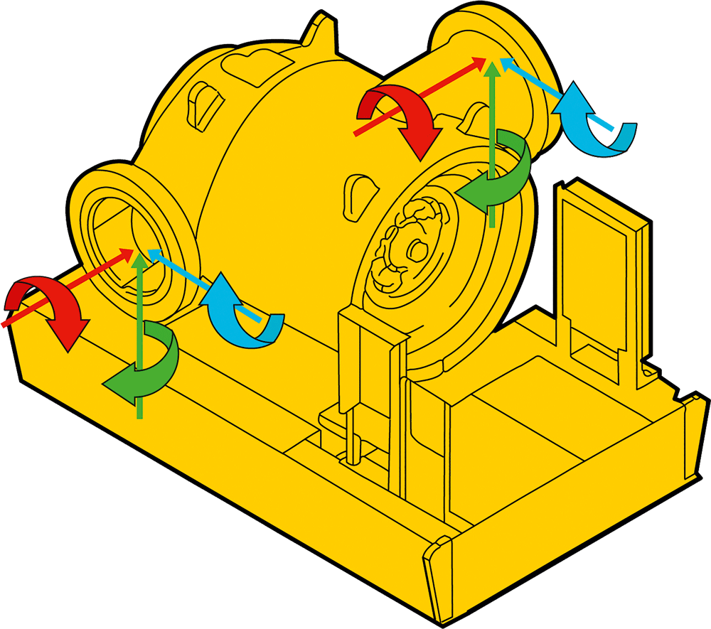
One of the most critical issues affecting rotating machines is casing distortion. This article delves into what casing distortion means, how it impacts machine performance, and why it is essential to address it in order to achieve reliable operation.
Casing distortion is not only one of the biggest problems for rotating machinery, but is also a very common one. But what does it actually mean? To explain it, we can use the famous analogy of a rocking table in the restaurant. This is a situation everybody can relate to. Due to an uneven floor or bad construction of the table, there is space under one leg which makes the whole table rock from one side to another. It is a problem that is easy to solve, just use a few napkins and the table will stay still.
The same happens when placing rotating machinery on a foundation that is not flat. Most rotating equipment is designed to be installed on a flat surface. At the manufacturer site, all machine feet are milled to be in a perfectly flat plane. When placing the equipment on a non-flat foundation or uneven sole plates, it will reproduce that rocking situation we just mentioned. That is what we call “soft foot”.
Tiny clearances, big impact
Rotating equipment consists of many parts: rotors, shafts, bearings, mechanical seals, impellers in compression chambers, just to mention a few. And these all have very small internal clearances. If a machine is bolted down on an uneven surface, the forces applied on the machine feet will change the casing geometry. As a result, these clearances will quickly change.
To fix a soft foot condition, is necessary to compensate everything above 0.05 mm. That is not much, if you consider the fact that the thickness of a human hair is between 0.06 mm to 0.08 mm! This is how little it takes to convert our new or newly overhauled machine into a victim of casing distortion.
Pipe connection issues
Another possible cause for casing distortion is pipe strain. Pipe strain can occur when the pipes are wrongly fabricated, and the connection flanges are not aligned. It can also be that the pipe supports are too high or too low, which creates large gaps between the connections. A common solution for this is to force them together, which will result in what we call nozzle load. This too will put a lot of stress on the machine casing. (The OEM will specify the allowed nozzle load on the equipment.)
The long-term consequences
So what kinds of problems can you run into if casing distortion occurs? Previously we mentioned the internal parts of rotating machinery, such as shafts. How do they get affected?
Well, shafts have mounted bearings to carry the rotating motion, and these bearings operate under designed loads. When casing distortion occurs, the shafts are put under strain and their positions change. That will affect the bearings by changing their designed load, and the rolling elements inside the bearing will move from designated race way. This is something that will seriously affect lubrication. The rolling elements of the bearing will push away the lubrication since there will be no space for it.
Heat will build up and produce more thermal expansion of internal components, which will gradually reduce their gap until, inevitably, failure occurs. (Changing the designed loads in the bearings will reduce bearing life by as much as 50%.)
Ensuring proper installation can make the difference between smooth operation and unexpected failure. As we have seen, all it takes is a minor gap to throw your machinery off balance. When it comes to rotating equipment, precision is a necessity.
Text: Roman Megela, Senior Reliability Engineer, Easy-Laser AB
Images: Easy-Laser AB
Subscribe to the free Maintworld newsletter here!
From Breakdowns to Breakthroughs: The Transformative Impact of Preventative Maintenance in Construction

The construction industry is the backbone of infrastructural development, and the machinery and equipment used in this sector play a pivotal role in ensuring projects are completed efficiently and on time. However, one of the most significant pain points in the construction industry is the frequent breakdown and inefficiency of equipment. These breakdowns not only lead to project delays but also escalate costs. Enter preventative maintenance – a proactive approach that addresses these challenges head-on, ensuring the longevity and efficiency of machinery.
What is Preventative Maintenance in Construction?
In the intricate tapestry of the construction industry, preventative maintenance stands out as a pivotal practice, underpinning the operational longevity and efficiency of critical machinery. It encompasses a systematic regimen of inspection, detection, rectification, and proactive measures to stave off potential equipment failures before they burgeon into tangible issues. This methodology transcends the rudimentary act of merely repairing a malfunctioning machine; it delves into a rigorous, routine-based examination and servicing paradigm, ensuring machinery remains in pristine working condition, thereby preventing unforeseen breakdowns.
Take, for example, a towering crane, an indispensable asset in a construction site’s arsenal. Rather than adopting a reactive stance and awaiting an inevitable malfunction, preventative maintenance adopts a proactive approach. This involves meticulous scrutiny of its intricate components, including cables, pulleys, and hydraulic systems.
The construction industry is the backbone of infrastructural development.
Activities such as lubrication, calibration of loose parts, replacement of components exhibiting wear and tear, and periodic software updates (if the machinery is digitally integrated) are integral to this regimen. According to a study by the Construction Equipment Management Program, regular preventative maintenance can enhance equipment life by up to 60%. Such a methodical and sophisticated approach not only ensures that the crane operates at its zenith of capacity but also significantly diminishes the probability of unanticipated operational downtimes, which can have cascading repercussions on project timelines and costs.
The Benefits of Using Preventative Maintenance in Construction
Significant Cost Savings in Many Areas of The Business In the intricate world of construction, where financial margins are often razor-thin, the role of preventative maintenance stands out as a beacon of fiscal responsibility. At first glance, the outlay for regular equipment upkeep might appear as an added expenditure. However, delving deeper into the financial matrix reveals a different narrative.
Unplanned equipment breakdowns, often resulting from neglect, can lead to exorbitant repair costs. According to the National Research Council, the financial implications of such reactive maintenance can be up to nine times more than a well-planned preventative approach. Beyond the direct repair expenses, the ripple effects of these breakdowns, such as project delays and potential contractual penalties, further strain project budgets.
Moreover, the longevity of machinery is intrinsically tied to its maintenance regimen. By investing in preventative care, construction firms can significantly defer the hefty capital outlays associated with equipment replacement. Research from the Construction Industry Institute underscores this, suggesting that machinery under a preventative maintenance umbrella can see its operational life extended by 20-40%. This elongation represents not just a delay in replacement costs but also ensures that the equipment operates at peak efficiency, leading to reduced operational costs.
Preventative maintenance stands out as a pivotal practice, underpinning the operational longevity and efficiency of critical machinery.
In summation, the financial wisdom of preventative maintenance in the construction sector is evident. While there’s an upfront cost, the long-term savings, both direct and indirect, make it an indispensable strategy for firms aiming for fiscal prudence and project success.
The Role of Preventative Maintenance in Ensuring Equipment Longevity in Construction In the construction realm, equipment longevity is not just a financial asset but a cornerstone for seamless operations and sustained business growth. At the heart of this longevity lies preventative maintenance—a proactive approach that ensures machinery not only endures but operates at its zenith, bringing manifold strategic benefits to construction entities.
Central to these benefits is the consistent operational efficiency that well-maintained equipment guarantees. The Construction Industry Institute underscores this, highlighting that machinery under a rigorous preventative maintenance regimen retains a vast majority of its operational prowess throughout its lifecycle. This directly translates to projects adhering to their timelines, fortifying a company’s reputation for reliability and punctuality.
Equipment longevity is not just a financial asset but a cornerstone for seamless operations and sustained business growth.
Additionally, the stability offered by equipment longevity, courtesy of preventative maintenance, means that operators gain in-depth familiarity with their machinery. This continuity ensures that operators master their equipment, leading to optimized performance and minimizing errors—a crucial edge in an industry where precision is non-negotiable.
Lastly, preventative maintenance not only ensures the equipment’s operational longevity but also preserves its intrinsic value. When the juncture arises to upgrade or divest, equipment that has been consistently maintained through preventative measures commands a premium in the secondary market, testifying to the enduring value of preventative care in the construction sector.
Enhanced Safety as a Result of Well-Maintained Assets In the construction sector, where the interplay of machinery and manpower is constant, safety remains paramount. Preventative maintenance emerges as a critical strategy to address the inherent risks, ensuring that equipment functions optimally and safely, thereby safeguarding the workforce.
The Occupational Safety and Health Administration (OSHA) has highlighted equipment-related incidents as a significant contributor to on-site injuries. However, the proactive approach of preventative maintenance can mitigate these risks. A study by the National Safety Council underscores this, revealing that up to 70% of machinery-related accidents could be averted through timely inspections and consistent maintenance. This proactive approach ensures that potential equipment malfunctions are identified and rectified before they escalate into safety hazards.
Moreover, the Bureau of Labour Statistics notes that the construction domain experiences a higher rate of fatal work injuries than many other sectors. Equipment malfunctions, unfortunately, play a pivotal role in these statistics. By integrating preventative maintenance into their operational protocols, construction firms can substantially diminish these incidents. This not only protects the workforce but also reinforces the company’s commitment to safety.
By proactively ensuring the health and efficiency of equipment, construction companies can create a safer environment for their employees, reduce potential liabilities, and deliver projects that stand as testaments to both quality and safety.
Environmental Benefits
The construction industry, with its heavy reliance on machinery and equipment, has a significant environmental footprint.
However, preventative maintenance emerges as a potent tool in mitigating these environmental impacts, offering benefits that extend beyond mere operational efficiency.
• Reduced Fuel Consumption: Machinery that undergoes regular preventative maintenance operates at its peak efficiency. According to the U.S. Department of Energy, well-maintained equipment can reduce fuel consumption by up to 10-15%. This not only translates to cost savings but also means fewer fossil fuels are burned, leading to a reduction in greenhouse gas emissions.
• Decreased Emissions: Emissions from construction equipment, particularly older models, can be a significant source of air pollution. The Environmental Protection Agency (EPA) notes that preventative maintenance, including timely oil changes, filter replacements, and engine tune-ups, can reduce emissions by up to 40%. This plays a crucial role in improving air quality, especially in urban areas where construction activities are frequent.
• Waste Reduction: Preventative maintenance also means fewer parts replacements and less waste. A study by the Construction Industry Research Board found that regular equipment checks can reduce waste from worn-out parts by up to 50%. This not only conserves resources but also reduces the burden on landfills.
• Resource Conservation: Efficient machinery requires fewer resources, from lubricants to replacement parts. The International Journal of Construction Management highlights that preventative maintenance can lead to a 20% reduction in the use of ancillary materials, further diminishing the industry’s environmental impact.
• Noise Pollution: Well-maintained equipment tends to operate more quietly, reducing noise pollution—a significant concern in urban construction sites. The World Health Organization has identified noise pollution as a major environmental health risk, and by ensuring equipment operates smoothly through preventative maintenance, construction companies can contribute to quieter, more liveable urban environments.
Preventative Maintenance as Part of a Comprehensive Maintenance Strategy
While preventative maintenance offers numerous benefits, it should not be viewed in isolation. Instead, it should be a part of a comprehensive maintenance strategy that also includes corrective maintenance (fixing things when they break down) and predictive maintenance (using data analytics to predict when a machine might break down). By integrating preventative maintenance into a broader strategy, construction companies can ensure that their equipment is always in the best possible condition, leading to efficient operations and successful project completions.
In Conclusion
The integration of preventative maintenance into a holistic maintenance strategy, encompassing both corrective and predictive maintenance, is emblematic of a forward-thinking, responsible, and sustainable approach to construction. Such a comprehensive strategy not only ensures the optimal performance of equipment but also safeguards the well-being of workers, the environment, and the broader community.
In the ever evolving and competitive arena of construction, companies that prioritize and invest in preventative maintenance position themselves at the forefront, setting industry standards and paving the way for a safer, more efficient, and environmentally conscious future. In essence, preventative maintenance is not merely an operational choice but a defining pillar for construction entities aspiring for excellence, sustainability, and enduring success.
Text: Charlie Green, Senior Research Analyst at Comparesoft Images: stockphoto
Subscribe to the free Maintworld newsletter here!
Best practices for storing electric motors
Storing an electric motor for more than a few weeks involves several steps to ensure it will operate properly when needed. For practical reasons, these are governed by the motor’s size and how long it will be out of service. Factors like the temperature, humidity and ambient vibration in the storage area also influence the choice of storage methods–some of which may be impractical for smaller machines or need to be reversed before the motor goes into service. With these things in mind, here are some common recommendations for storing motors.
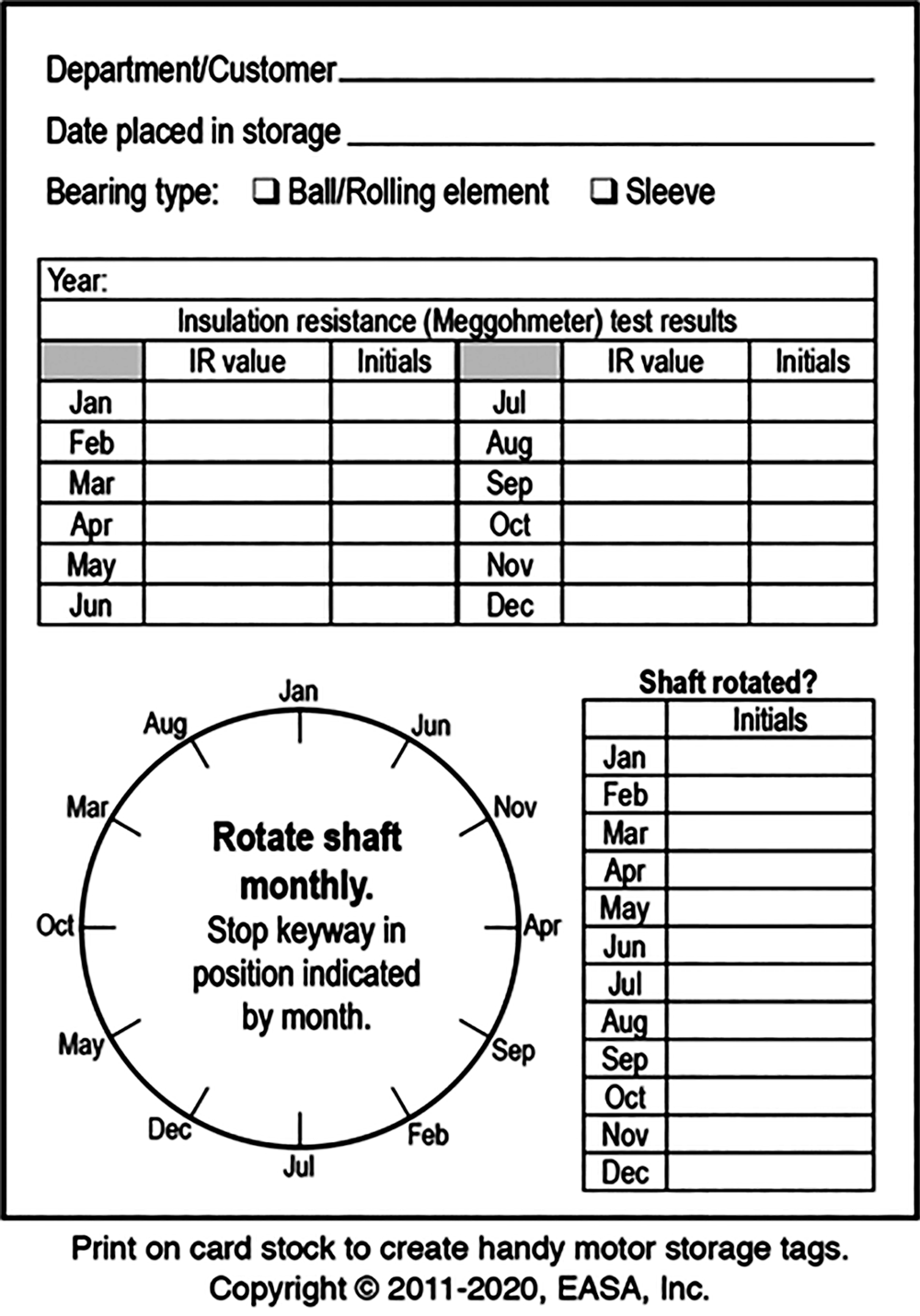
Good, readily available records are essential for any motor storage program. One method is to attach a form like that in Figure 1 to each motor to document the storage dates, maintenance procedures completed, and the results of all tests performed during the storage period.
For motors in long-term storage, a good practice is to replace the form annually (or at other designated intervals). Store electronic copies of the previous forms for future reference, or simply keep them in an envelope attached to the motor.
Storage conditions
Short-term storage. Motors that will be in storage for just a few weeks primarily require protection from the weather (see “Indoor storage” and “Outdoor storage” below) and ambient vibration (more on this later).
Long-term storage. Motors slated for several weeks to several years in storage and all above-NEMA size machines require additional preparations to protect their machined surfaces, bearings and windings.
Indoor storage. If possible, store motors indoors in a clean, dry area. Place horizontal machines in a horizontal position and vertical motors in a stable vertical position.
Unless the storage area is climate controlled, prevent condensation from forming inside the motor by energizing the space heaters (if supplied) to keep the windings 5-10°C (10-20°F) above the ambient temperature. (For other ways to prevent condensation, see “Special care for windings” below.)
Outdoor storage. Don’t! Seriously, if a motor is too large to store indoors, it is likely to be a very expensive machine. It’s worth the cost to construct an enclosed storage facility. When outdoor storage is absolutely necessary, protect the motor with a waterproof cover (e.g., a tarp), allowing a breathing space at the bottom. Wrapping it tightly in plastic and placing it outdoors will cause condensation to form inside the motor due to the temperature extremes and humidity.
Outdoor storage also requires preventive measures to keep out rodents, snakes, birds or other small animals that can damage the winding insulation. If insects are prevalent, keep them from blocking ventilation and drain openings by loosely wrapping the motor and covering all openings.
Shafts and machined surfaces
Apply a viscous rust/corrosion inhibitor (e.g., LPS2, Techtyl 502C or RustVeto) to exposed machined surfaces and sleeve bearings, allowing it to remain intact throughout the storage period. In humid and rainy/snowy environments, have the service center paint as much of the motor’s interior surface as practical, and coat the windings with a topical fungicide in tropical environments. (Note: Disassemble the machine and inspect the sleeve bearings before placing it into service.)
Bearing protection
Grease-lubricated motors. For long-term storage, completely fill the bearing cavities with compatible grease to prevent rust and corrosion staining that can occur if moisture collects between the balls and races.
Oil-lubricated motors. Do not ship or move these motors with oil in the reservoir. After placing the motor in storage, fill the reservoir with enough oil to cover the bearings but without overflowing the stand tube or labyrinth seal. Fill sleeve bearing machines to just below the labyrinth seal and vertical motors to the “max fill” line.
The oil should contain a rust and corrosion inhibitor and be moisture free. Check it every three months by drawing a sample from the drain. Since water weighs more than oil, any moisture will be evident.
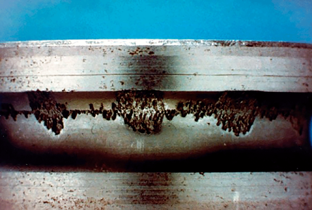
Ambient vibration. This can damage motors, even when they are not rotating. Proximity to rail lines, busy roads, and/or production floors can all contribute to the ambient vibration. Even low-magnitude vibration, over time, can damage bearings while they are stationary–e.g., false brinelling (see Figure 2). Solutions vary. For example, one mill that had ambient vibration from nearby machinery stored its motors on scrapped conveyor belting.
False brinelling damages the bearing race at uniform intervals matching the spacing of the rolling elements. Although the damage initially may appear slight or even invisible to the naked eye, it often progresses rapidly once the motor is in service.
Shaft rotation. Turning the motor’s shaft at least monthly during long-term storage redistributes lubricant on machined surfaces to inhibit corrosion. Motors with ball or roller bearings also benefit from monthly rotation, since the rolling elements stop in different positions each time. Larger, 2-pole machines require more frequent attention than smaller (NEMA-frame) machines.

Motors with spring-loaded spherical bearings are more difficult to turn, but they still require manual rotation to coat the bearings with oil. With sliding plate (i.e., Kingsbury) bearings, lift the shaft before rotating it–from below with a short jack and a bearing ball centered on the shaft, or from above with an overhead crane and eyebolts. To avoid bearing damage, be careful not to lift the shaft more than a few mils.
Machines with heavy rotors and long frames in ratings of about 2000 hp (1500 kW) and larger sometimes require more frequent (weekly) rotation to prevent shaft bowing caused by the weight of the rotor. As an extreme example, power plants often keep large turbine generators rotating slowly all the time to prevent sag. While it is uncommon, removing and vertically suspending the rotors of very large critical machines also can prevent sagging.
TIPS FOR TRACKING IR TEST RESULTS
Attach a card to each motor and record the IR, temperature and date of each test.
TIPS FOR ROTATING THE SHAFT
Rotating the shaft keyway position in 150-degree increments every month makes it easy to spot a neglected motor. If you visualize a clock face, each increment represents 5 hours: For example, if the keyway position for September is 12:00, October will be 5:00, November will be 10:00, and so on. This puts the rolling elements in a different position each time and avoids rocking the rotor back and forth between just two positions (see Figure 1).
TIPS FOR OIL-LUBRICATED MOTORS
Never move a motor with oil in the reservoir. If oil sloshes over the stand tube, it could contaminate the windings or even initiate capillary action that can siphon oil from the chamber. Before putting the motor into service, always drain the oil and replace it with compatible lubricant. (Drain it. Move it. Refill it.)
Special care for motor windings
Methods for preventing condensation. Motor windings must stay clean and dry to keep the insulation from degrading. Unless the storage area is climate controlled, condensation can form in the motor if the temperature of the winding dips below the dew point. As mentioned earlier, the usual way of avoiding this is to keep the winding 5-10°C (10-20°F) above ambient temperature.
If the motor has space heaters, energize them while it is in storage; if not, add them. Another option is to use the windings as a resistance heater by supplying low-voltage DC current (approximately 8-12% of rated amperage). An energy-saving alternative is to lower the dewpoint of the storage room with a dehumidifier.
Insulation resistance (IR) tests. Measure and record the IR of the winding(s) before storing a motor even a few weeks, and again just before putting it in service (see Figure 3). Correct all IR readings to a standard temperature and address any decrease in IR before installing the motor. If a motor will be in storage for a long time, take IR readings annually.
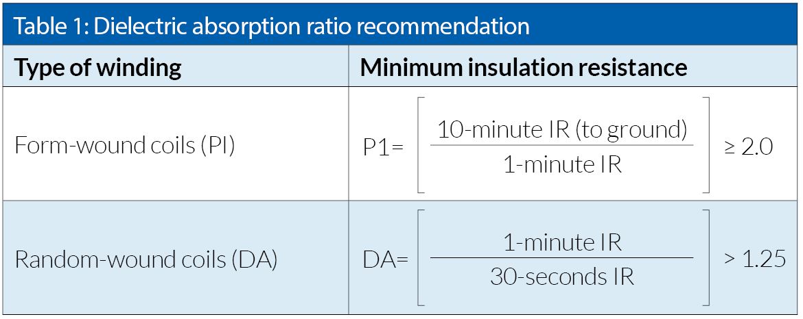
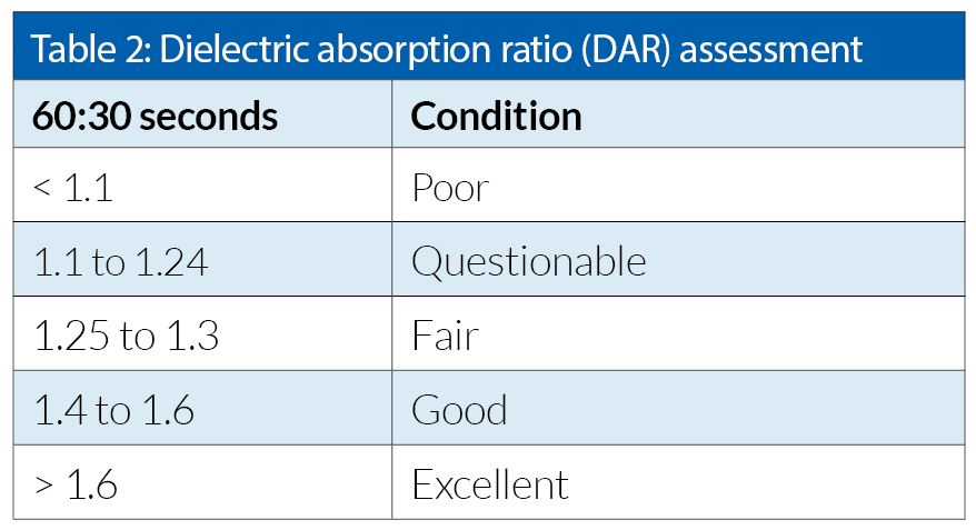
Polarization index (PI) and dielectric absorption ratio (DAR) tests. For form coil windings, conduct a PI test in addition to the IR test. The PI test variables skew results for windings with lots of exposed conductor surface area, so use the DA ratio test for random windings and DC armatures (see Tables 1 and 2).
If the windings need to be cleaned and dried, measure the IR again. If it is greater than 5000 megohms, disregard the PI (see IEEE 43); otherwise, recalculate the PI.
Insulation resistance (IR) tests. Measure and record the IR of the winding(s) before storing a motor even a few weeks, and again just before putting it in service (see Figure 3). Correct all IR readings to a standard temperature and address any decrease in IR before installing the motor. If a motor will be in storage for a long time, take IR readings annually.
Polarization index (PI) and dielectric absorption ratio (DAR) tests. For form coil windings, conduct a PI test in addition to the IR test. The PI test variables skew results for windings with lots of exposed conductor surface area, so use the DA ratio test for random windings and DC armatures (see Tables 1 and 2).
If the windings need to be cleaned and dried, measure the IR again. If it is greater than 5000 megohms, disregard the PI (see IEEE 43); otherwise, recalculate the PI.
Carbon brushes
DC machines, wound-rotor motors and some synchronous machines have carbon brushes. For long-term storage, lift the brushes away from the commutator/slip rings to prevent a chemical reaction (sometimes called “photographing”) that can discolor the underlying commutator or slip ring. When practical, store the springs in the relaxed state to prevent a gradual loss of spring pressure.
Putting the motor into service
To ensure proper operation when removing a motor from storage and putting it into service, perform the following:
- Use compressed air to clean the outside of the motor, and visually inspect it.
- Assess the condition of the insulation system by measuring the IR with a megohmmeter.
- Oil-lubricated motors:
- Drain the oil before moving the motor to the installation site.
- If there is water in the oil, check for and replace any rusty bearings.
- If sleeve bearings received a protective coating, disassemble the machine and clean the bearings with an appropriate solvent before putting the motor into service.
- Fill the oil reservoir to the correct running level after installing the motor.
- Grease-lubricated motors:
- Moisture in the grease usually indicates rust-damaged bearings that need replacement.
- After several years in storage, the grease probably will be hard and the drainpipe will be plugged; usually it is best to disassemble the motor, remove the old grease and repack with fresh, compatible lubricant.
- Run the motor 10-20 minutes without the drain plug to purge excess grease.
- Vibration and alignment:
- If the storage area has ambient vibration, inspect and replace damaged bearings before installing the motor.
- After installing and aligning the motor, document the uncoupled baseline vibration levels; check the levels again after a week or two of service.
- For motors with rolling element bearings, check for bearing fault frequencies in the vibration spectra.
- On large machines that are susceptible to shaft sag, monitor the vibration levels during startup to avoid catastrophic damage.
High-cost machines obviously justify more precautions than inexpensive, readily available motors. What is not always apparent is that some “smaller” motors are equally important to production and can have enormous consequences if they fail.
References
IEEE Std. 43-2013: Recommended Practice for Testing Insulation Resistance of Electric Machinery. Institute of Electrical and Electronics Engineers, Inc. New York, NY, 2013.
Text: Chuck Yung, senior technical support specialist at EASA, Inc., St. Louis, MO USA Images: EASA, stockphoto
Subscribe to the free Maintworld newsletter here!
How much air leaks really cost – Leak Survey Examples
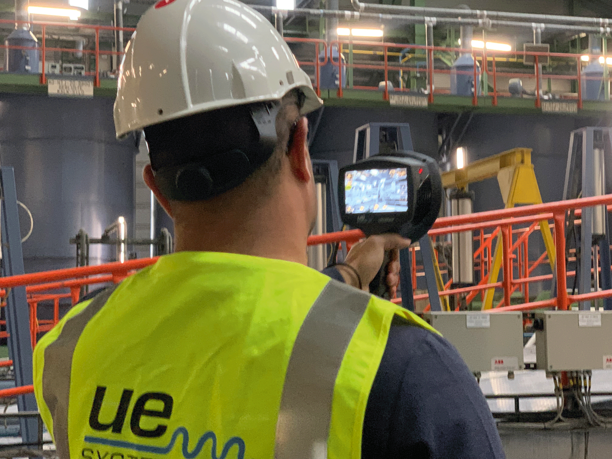
We all know that compressed air leaks are a huge source of energy (and money) waste, but do you know how much they really cost? After conducting around 60 surveys in different facilities from different industries, using an ultrasound camera, we concluded that the average leak would cost around 1200€ per year. When you think that any industrial site will have dozens or even hundreds of leaks, you can quickly realize the savings potential.
As energy prices rose up to historical peaks, compressed air leaks have also become more expensive than ever. In these times, finding and repairing those wasteful leaks must be a priority for any maintenance team looking to cut down on energy waste.
Knowing that, on average, approx. 10% of all energy supplied to an industrial facility will be used for compressed air; and that the average leak rate across a site in industry is 30%, you can quickly realize that compressed air leaks will be one of the greatest sources of waste in industry.
How to conduct effective air leak surveys
It is well established that using ultrasound inspection instruments is the most effective way of finding leaks. Digital instruments will also record the decibel level at the leak point, which will be the basis to calculate the leak cost and elaborate reports.
Normally these are handheld and listen-only instruments – still very effective in detecting leaks, but more recently, with the deployment of ultrasound cameras, you can also see the leaks, in real time, turning leak surveys into a much more effortless and quick task.
Thus, when considering that:
1. Air leaks are more expensive than ever – one leak costs an average of 1200€ per year
2. Finding air leaks is now easier and quicker than ever
We can conclude that having an ultrasound camera is a no-brainer for most industrial facilities.
As these cameras are working by simply showing the leaks on the screen, you can find dozens of leaks in minutes.
Leak Survey Examples & the cost of leaks
The examples of leak surveys below were conducted using the UltraView camera from UE Systems, one of the most advanced leak detection devices available today. You can clearly see how, in a matter of hours (sometimes even minutes), the UltraView can detect and quantify leaks worth thousands.
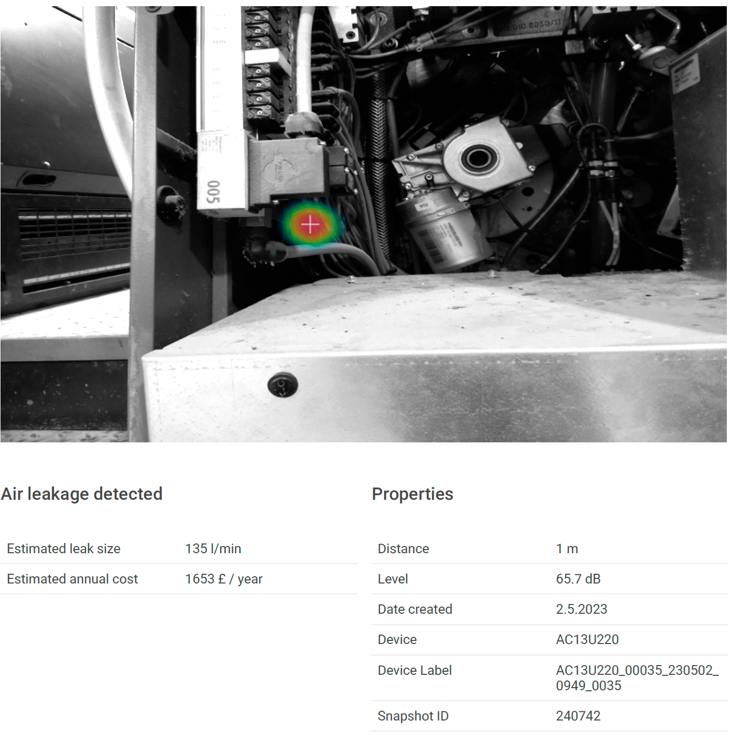
1. Commercial Printing Facility – 1 single leak costing 1650€ per year
The printing industry uses a lot of compressed air (especially when printing newspapers and magazine, like this facility), making these facilities perfect candidates for an efficient leak detection device. With a proper leak detection program in place, cost avoidance can be huge. One single leak was estimated to cost 1650€ per year! A 30-minute survey at this facility carried out with the UltraView detected 6 leaks amounting to a cost of 7000€ per year. This is only a small part of the total amount of leaks estimated at this site, since almost all printing machines will need compressed air.
Besides the energy waste, these leaks bring other issues: as leaks on the printing machines will bring down the system pressure, this will compromise the printing quality. Thus, finding and repairing leaks in the printing industry is not just a matter of energy savings, but also of assuring the final product quality.
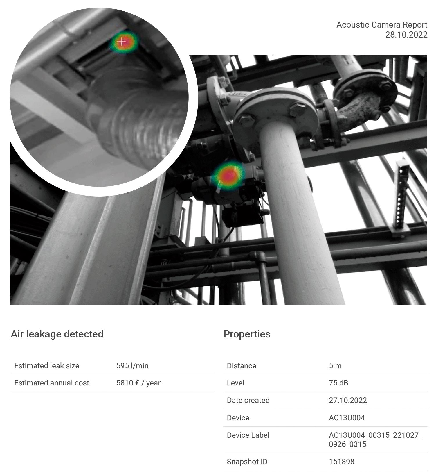
2. Costly compressed air and argon/nitrogen leaks found at pharmaceutical company
Pharma uses a lot of compressed air, as well as special gas, which means leaks can quickly become a huge source of energy waste. We could attest exactly that when surveying a pharmaceutical plant using the UltraView. During the demonstration we were able to pinpoint and report 29 compressed air leaks in about 2 hours of survey.
The total cost for these leaks is estimated at a costly 28313€ per year. This includes some major leaks, including one huge leak which was undetected so far and was costing the company 5809€. The UltraView was able to easily pinpoint it even at a 5 meter distance.
Besides compressed air, we could also detect some very expensive argon and nitrogen leaks. Special or innate gas leaks can become quite expensive, as the price for these is usually 3 or 4 times more expensive than compressed air.
In the video we can see how the UltraView could find an argon leak at a tank. This is a leak losing 9 liter per minute of argon, meaning that, if it would be left undetected, the tank would be empty in about 3 to 4 days.
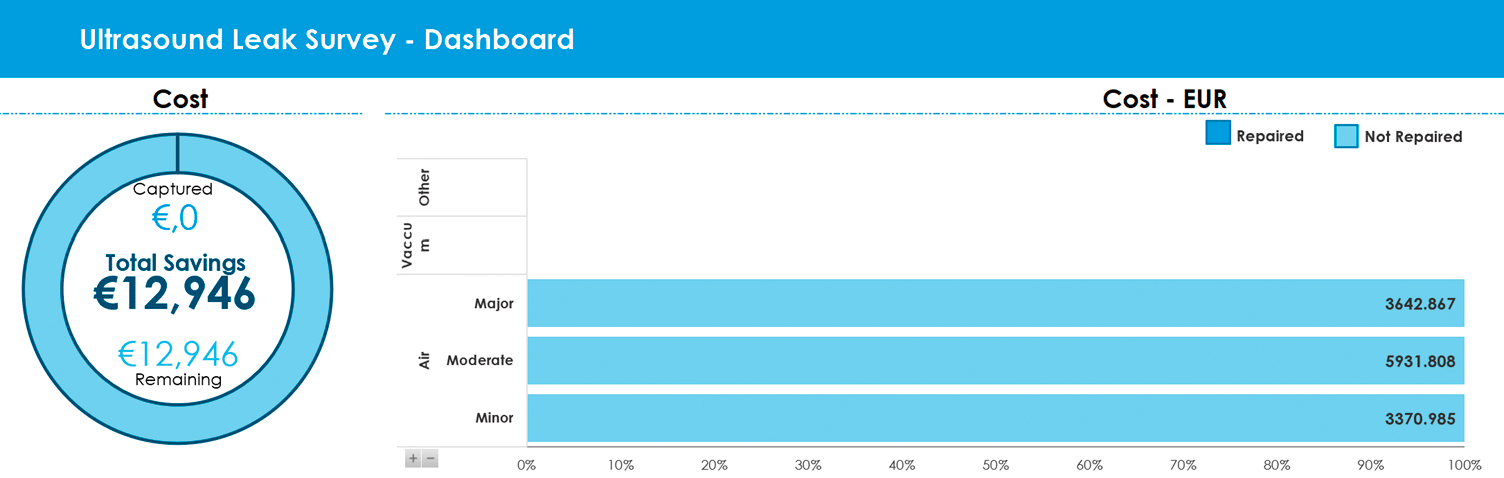
3. Food packaging plant: detecting compressed air, vacuum and vent leaks
At a food packaging plant we did a quick survey using the UltraView camera. Packaging facilities normally rely heavily on compressed air, so it was no surprise that we were able to quickly find 22 leaks amounting to almost 13000€, including 2 leaks at hard to reach locations which we could easily detect even at a 5 meter distance. These would be much more difficult to pinpoint using traditional listen-only ultrasound instruments.
On top of that, the UltraView could also detect 3 vacuum leaks and 1 leak in the ventilation system, as we can see in the video. Vacuum leaks are a big issue in many industries, as they are very hard to detect and can quickly lead to product quality loss and increase in production time.
Also, interesting to note that leak at the ventilation system, which is not a typical application for the UltraView but was very important at this facility, since the maintenance team wants to assure the vents are completely sealed, otherwise dangerous gas might not be expelled from the facility as they should.
Peter Boon, Product Specialist, UE Systems
Subscribe to the free Maintworld newsletter here!
Redefining Industrial Maintenance in the Tech-Driven Era: From Mandatory Cost to Value Generator
New intelligent technologies offer numerous opportunities to improve the efficiency of business operations in various sectors – including the maintenance industry, However, the ongoing technological revolution also raises concerns such as – will there be enough jobs in the sector in the future? Is it possible to guarantee the operational reliability and safety of fully automated production plants of the future?
Juha Ryödi, Vice President of Life Cycle Services at Vaisala Oyj, sees that technological change will inevitably affect not only the work of maintenance professionals, but also the image of the maintenance industry. This is a good thing, especially now that the industry fears a growing labour shortage in the future due to retirement trends and cuts in training spending in technical fields.
Ryödi says that new modern technologies and maintenance tools are making the job of a maintenance technician more specialised than routine tasks. New technologies are also making the industrial maintenance sector an attractive career option for young people entering the engineering field. The potential of machine vision, for instance, is being widely explored and tested in the manufacturing industry today. Many believe that it has almost limitless potential for use in condition monitoring and, for example, in improving the efficiency of logistical operations.
Despite recent progress, technological advancement has not yet reached its full potential.
According to Ryödi, new technologies are also bringing a new level of transparency to maintenance operations. Consequently, the results of maintenance activities are more readily visible to other organisations.
– I think maintenance is becoming a fascinating field because it was a somewhat “dark
area” for many years. Thanks to today’s technologies, we can now view maintenance as a productive unit that adds value to the company, rather than just being seen as an obligatory expense, Ryödi says.
Technological progress has not yet reached its full potential
Despite recent progress, technological advancement has not yet reached its full potential, Ryödi states. Much of this is because companies have not yet been able to fully monetise their maintenance services to customers because the benefits of maintenance are more long-term than quick wins.
At the same time, the maintenance sector – like many other sectors – still struggles with the challenge of recruiting sufficient qualified personnel, especially tech-savvy younger generations equipped with the skills needed to adopt new technologies effectively.
– However, as the baby boomer generation retires, skills and knowledge must be transferred and replicated within organisations. This will require adopting different systems and, for example, new digital tools. It will also create future competitive advantage and scalability, which will act as drivers for the evolution of the service business, says Ryödi.
The time for cost efficiency is here, Ryödi continues. On the other hand, industry is undergoing a major energy transition that is creating new investment needs. This situation is creating even more demand for the efficiency of maintenance operations and, ultimately, the adoption of new technologies.
– Traditionally, industrial maintenance has been viewed as a necessary but costly function. It typically involved routine inspections, repairs, and downtime management. However, the advent of cutting-edge technologies is reshaping this narrative, turning maintenance from a liability into a strategic asset.

Modern facilities are hybrid
Factories of the future are forward-looking manufacturing facilities that take full advantage of Industry 4.0 opportunities. Factories of the future focus on digitising their processes, making the most of new production technologies, and managing energy and materials increasingly circularly. What do such factories look like today?
Ryödi stresses that although the word “hybrid” is currently a very overused term, it could be used as a metaphor when describing factories of the future.
– Increasingly, factories are looking for solutions where technology enables as much as possible but still under human control in some aspect – either in terms of physical assembly or through a process control system. The Covid pandemic has greatly boosted the potential for, for example, remote monitoring. Meanwhile, various types of measuring and data collection are a growing trend that allows scaling knowledge in factory control, for example.
What is the role of machine learning in factories of the future?
Machine vision is a very quality-focused technology in industry, and many applications are still related to quality, quality monitoring and reporting, Ryödi says.
Machine vision still has much potential, especially when combined with AI-based decision-making, as different cameras and sensors are becoming more accurate and faster. One exciting area to follow is chip manufacturing and how machine vision will be able to serve – and potentially control – these very high-frequency processes even more efficiently in the future.
Are manufacturing facilities moving towards full automation?
Ryödi notes that there are still relatively few factories that can be called fully automated due to the level of intelligence of the technology and its replicability in relation to repeatable processes. Meanwhile, manufacturing chains are currently struggling a bit to find their place on a global scale. This affects the level of automation in industry because increasing the level of automation means making significant investments, and large investments almost always mean showing a return on investment.
However, at the same time, evolving technology is enabling more and more, and as component shortages ease, the prices of industrial robots, for example, will continue to decline and accelerate their uptake. Highly repeatable and heavy processes have already achieved a high degree of automation. However, how, and when they reach a fully automated level remains to be seen.
How will the role of the maintenance manager change in a fully automated factory?
Modern technologies are making the industrial maintenance sector an attractive career option for young people.
The role of a maintenance manager is crucial in ensuring the smooth and efficient operation of machinery, equipment, and facilities within an organisation. Their primary responsibilities have traditionally included a wide range of tasks to preserve assets, minimise downtime, and promote safety and reliability.
Ryödi anticipates a definite shift in the role of maintenance managers within organisations as automation levels continue to rise.
– I think there is a clear trend here to be more proactive in understanding and planning. Many industries, such as pharmaceutical manufacturing, will soon move to so-called continuous processes instead of batch production, and this will also change the role of maintenance to be more proactive and planned.
– In the future, the maintainer will have to be able to interpret more data and better plan their work, and, on the other hand, to carry out and document it very accurately. However, many things remain constant, such as understanding mechanics or electrical engineering. This is still highly valued.
– A skilled workforce enables us to overcome the small margins that distinguish us from other countries in comparison, Ryödi says.
All eyes on information security
Juha Ryödi adds that although technological change will benefit the sector, it is not without risk. One of the biggest fears associated with increasing automation is currently security.
– In my opinion, information security is the most significant single risk now. Whenever we talk about automation and its connectivity and integration with different systems, we must consider information security and its requirements.
The so-called Hyppönen’s law is also good to remember in maintenance (If It’s Smart, It’s Vulnerable – Mikko Hyppönen), Ryödi says. Mikko Hypponen is a global security expert, speaker, and author. He is the Chief Research Officer at WithSecure and Principal Research Advisor at F-Secure.
Maintenance tools, such as maintenance systems, have become much more cloud and web-based, and on the other hand, many practical tools or customer processes are connected to the web.
– A major transformation is taking place, but so far there have been relatively few security incidents. This is partly because the interconnection of different systems and tools is just reaching its acceleration point, and partially because industrial companies are taking information security risks very seriously. In maintenance, it is also worth remembering that the responsibility of maintenance workers is often greater than that of many others. Maintenance personnel may have greater access to many systems, which puts them in a more critical position.
Juha Ryödi, Vice President of Life Cycle Services at Vaisala Oyj

Juha Ryödi has studied automation and electrical power engineering alongside his job and commercial studies (MBA). He started his career at the automation and power engineering technology giant ABB as a plant engineer in the year 2000. After ABB, Ryödi joined Sataservice Oy, a provider of maintenance and optimisation services to industry.
“I have been working more or less continuously in the engineering field since I turned 18,” Ryödi says.
In 2017, Ryödi joined Vaisala to be responsible for technical services globally. Ryödi is a keen sportsman and played competitive ice hockey in his youth.
Text Nina Garlo-Melkas Images Vaisala Ltd., SHUTTERSTOCK
Subscribe to the free Maintworld newsletter here!
Latest