Ensure Availability, Cost Efficiency and Positive Climate Impact with Modernized Drives

Modernization allows older drives to achieve all the benefits of modern technology – lower harmonics, and higher serviceability and uptime.
According to a recent ABB survey, unplanned downtime can cost typical industrial businesses up to $125,000 per hour. The modernization and the revitalization of existing equipment offers an alternative solution to full, and costly, end-of-life system replacement.
Modernization in action
Take the example of a variable-speed drive – which controls the speed and torque of a motor to match the exact demands of the task. With modernization, you can seamlessly transition to the latest technology, while keeping the drive’s cabinet and cabling, and replacing only what is needed. This approach can be carried out with minimum interruption to normal operations, often during a scheduled maintenance period.
Modernization allows older drives to achieve all the benefits of modern technology – lower harmonics, and higher serviceability and uptime. Even obsolete drive equipment can be modernized, restoring reliability and potentially enhancing performance. This solution minimizes the total investment required, while extending the drive’s life by 10-15 years.
Modernization projects present a circular alternative to the linear “take-make-waste” economy.
Moreover, replacing only necessary components reduces waste and the emissions associated with transporting and packaging the other components. This means that modernizing a drive can avoid up to 55% of carbon emissions compared to a full replacement.
The case of Jämtkraft
Jämtkraft, the Swedish utility company, is a good example. By modernizing nine of its existing drives to bring them into the active phase of their life cycle, it avoided 10 tons of CO2 emissions. This is equal to the emissions of driving a gasoline-powered car for five years or 57,000 kilometers. Since existing cabinets were used, no substantial modifications were needed to the previous infrastructure, reducing the overall expenditure for the project.
Drive modernization boosts paper mill’s uptime
Mondi SCP, the largest wood processor and the largest producer of pulp and paper in Slovakia, modernized its aging drive units with a retrofit solution.
First, experts selected the best timing for the modernization, based on the lifecycle phase of the existing drives. The older drives were then modernized to newer technology and there was no need to replace the existing infrastructure, including cabinets, cabling, electrical machinery, and automation systems. This reduced the overall investment needed for the project.
By aligning modernization services with routine maintenance schedules, the project was completed within a week and came with minimal disruption to regular operations.
A perfect alternative to the “take-make-waste” economy
The linear economy – where we take resources, make products, and then create waste when we discard them – harms the environment. It relentlessly drives global challenges such as climate change and biodiversity loss.
Modernization projects present a circular alternative to this linear “take-make-waste” economy. They promote circularity as they focus on minimizing waste, optimizing resource use, and reducing the environmental impact of production and consumption. This is because modernization solutions promote the reuse of materials that would otherwise contribute to landfills. In this way, they aim to create a closed-loop system where products, materials, and resources are used, refurbished, manufactured, and recycled throughout their lifecycle.
Switching from linear to circular economy
This is why products must be designed with circularity in mind. Efforts need to be focused on designing equipment and systems in a way that enables proactive services, such as modernization, to be carried out. This includes creating products that are durable, repairable, and made with materials that can be easily recycled.
Similarly, businesses have a responsibility to purchase circular products and services to help invigorate the circular economy. This also benefits businesses’ operations – as shown here, proactive services act as an alternative to scrapping products altogether, enabling businesses to avoid CO2 emissions, downtime, and waste.
The Case for Industrial Energy Efficiency
A new report from the Energy Efficiency Movement (EEM) shows how companies can take immediate action as industry faces an unprecedented challenge to meet global carbon emission targets and meet growing demand. EEM is a global forum, founded by ABB, which now includes more than 400 organisations and shares ideas, best practices and commitments to create a more energy-efficient world.
The Case for Industrial Energy Efficiency, published in November last year, aims to provide business leaders with a key insight into 10 advanced technology-based measures that have a significant impact on costs and emissions and can be implemented quickly without complex or expensive projects.
According to the International Energy Agency (IEA), doubling efficiency by 2030 could reduce greenhouse gas emissions by almost a third from current levels.1 For industry, this is a huge opportunity. The Energy Efficiency Movement estimates that if the 10 simple measures outlined in this guide were applied across all industries, they could save 1.5 gigatonnes of carbon dioxide emissions per year by 2024 and 4 gigatonnes by 2030.
Images: ABB


Subscribe to the free Maintworld newsletter here!
Implementation of autonomous maintenance

Autonomous maintenance is another term used when operating personnel are responsible for performing minor maintenance tasks. You may have heard the terms Total Productive Maintenance (TPM), Operator Essential Care, Operator-Based […]
Autonomous maintenance is another term used when operating personnel are responsible for performing minor maintenance tasks. You may have heard the terms Total Productive Maintenance (TPM), Operator Essential Care, Operator-Based Maintenance, etc., but at the end of the day they all mean the same thing.
Autonomous maintenance can be implemented in many ways. We use the terms autonomous maintenance (AM) and user-based reliability (OBR) interchangeably here.
Involving operators in reliability is technically very simple, but it can be very challenging from a people perspective. This means that it is easy to work out what should be done and how to do it, but in many cases it can be almost impossible to get people to do the tasks. It is therefore worth spending a considerable amount of thinking time on the problem: “How do we as a company get people to do what we want them to do in terms of equipment maintenance?”. The answer to this question will vary from country to country, industry to industry and local culture to local culture, but we (IDCON) will share some of our experiences.
“People don’t mind change, but they mind being changed by others.”
So one of the basic concepts of AM/OBR deployment is “participation”. The level of participation needs to be considered before starting an OBR implementation, because the more people are involved, the longer it takes to decide what and how to do something. At the same time, greater participation increases ownership and acceptance.
As a leader, you need to decide when and to what extent to involve people in order to achieve the right balance. In general, leaders should make decisions about what is the right thing to do. For example, management should decide on the scope of the programme and the outcomes they want from the programme, while smaller groups can be tasked with figuring out how to do certain tasks, many people can help build the information in the work system once the design is done.
What will this work system look like when it is finished?
Before dividing people into tasks, it is important to paint a picture of what the finished product will look like. If you, as a leader, don’t paint a clear picture of what AM/OBR will look like when it is complete, how can you expect your organization to move in the right direction? The sad truth is that most managers just say they want operations to take over the maintenance tasks, and everyone comes up with their own version of what it looks like. Below are things to consider and questions to ask as you begin to develop your AM programme:
#1 Define exactly what tasks you want the functions to do and what they currently don’t do, or are doing but need to improve.
- Detailed equipment checks
- Equipment cleaning (how detailed)
- Running equipment at maximum speed, maximum reliability or maximum throughput
- Whether minor maintenance tasks are carried out, if so what exactly
- Whether problem solving and root cause analysis is led or participated in
- Whether only hourly workers are needed or whether involvement of paid functions is also required
- Should operations management improve reliability through better joint prioritization of maintenance work and joint scheduling with maintenance?
#2 Determine whether operators should have documented inspection routes and how inspections are performed.
- How detailed should inspections be?
- Should they have handheld devices (tablets, smartphones, etc.) to track problems and measurements?
- What inspection tools are needed?
- Who will be responsible for managing and cleaning up inspection routes to ensure they get done?
- Who will carry out the inspections and for how long? Does it vary by shift and task?
#3 What training and who needs to be trained?
- Are operations supervisors and managers trained to operate and inspect equipment?
- What training materials, training modules or courses are needed? Or do you assume that operators understand how pumps, motors, regulators and hydraulics work and what signs of failure these parts show?
#4 What happens when equipment is installed or removed?
- Who is responsible for updating operators’ routes?
- Who is responsible for updating inspection instructions?
- There are, of course, many more questions, but by answering questions like the ones above, you will begin to paint a picture for your organization of what the system looks like.
Don’t forget communication
Once the picture is painted, don’t forget to communicate this future state to the organisation. Many organisations do not have effective communication channels. Typical communication is that top management communicates to middle management, and then it is assumed that middle management will spread it to lower management and so on. Both the content and the scope of the message are almost always poorly communicated. Try to ensure that the vision for the future is communicated clearly and professionally. Read more about OEE and benchmarking maintenance costs.
Before starting any AM process, you need to be aware of what is happening to resources and costs.
Implementation plan
The implementation plan does not describe what the final product will look like. The implementation plan describes the tasks needed to achieve the objective. Most implementation plans usually consist of many small tasks, I have outlined in this article some important tasks to consider.
A simple but structured documentation process is needed. There is not enough space in this article to explain the whole documentation process, so we have decided to list a few key points.
Have a logical approach to your maintenance method. Methods include Operate to breakdown Fixed Time Maintenance Condition Based Maintenance Ensure that inspection frequency is based on the estimated Failure Development Period (FDP) and not on criticality.
Use standards
Use standards for standard components. For example, a typical air cylinder is inspected 99% of the time in the same way regardless of location or application. The same is true for most components such as pumps, motors, filters, switches and others. Set points such as temperatures and pressures may vary, but the same point is measured.
Explain to inspectors how and why the inspection is being carried out. Our condition monitoring standard is designed to do this for you. You can download an example from our website: AC motor and coupling wheel.
Do not use Reliability Centered Maintenance (RCM) to determine each individual inspection. Use RCM when it is necessary for safety, when the system is complex, or when you want to train people in reliability theory. RCM is too cumbersome and overwhelming to determine the basic inspections for the entire site.
Choose logical inspection routes
Inspection routes should include all equipment in a logical walking order. You should not do a route with only pumps, for example. If you do it component by component, the operator will have to walk the same area many times. Once pumps, once valves, once hydraulics, once piping, once tanks, once regulators, once vacuum pumps, etc. An operator never walks an area multiple times, so if you don’t mix multiple equipment types in one trip, you will miss many critical parts and end up doing only motor inspections or only valve inspections.
Why use keywords in inspections?
We have found it useful to base operator inspections on standard component instructions. Each instruction consists of several keywords. A standard instruction is what the inspector carries with him in the field on paper or on a laptop. For example, an electric motor standard inspection may contain the following keywords: ventilation, detailed cleaning, water/humidity, motor base, electrical lubrication, temperature, noise and vibration.
The keywords are for memory refreshment only, not as instructions. If the inspector does not know how or why to do the inspection, he refers to the CMS. The CMS explains exactly how and why each inspection is carried out. The CMS can be available in a booklet in the inspection room or other public area, or they can be stored as PDF files on a shared server.
What about measuring points?
We believe that the general rule is to collect only the measurement points that are used. It is common for factories to collect as many measurement points as possible for each component. When the AM system is started, no one ever looks at the data. Do not collect more points than the plant can handle and has time to analyse. Why not start with 25 measurement points in each area and see if the data is used. If they do, add more data points. A good way to kill the AM/OBR process is to ignore the fault reports and the data collected.
What about resources?
Address resource issues before implementing an OBR programme. Before starting any AM process, you need to be aware of what is happening to resources and costs. The process will save you money, increase production efficiency (through reliable equipment) and reduce your workload in the long run, but in the short run it can do the opposite.
Why? By logical deduction, the maintenance backlog increases when the AM system is started because more problems are found than before. It costs money to perform maintenance work. Once the backlog is dealt with, the reliability of the equipment starts to improve (assuming that the prioritisation is done correctly). As reliability starts to improve, costs will fall because the plant will make fewer repairs, use fewer parts and have fewer interruptions to production schedules.
Getting management to commit to the programme
Plant and company management need to understand the basics of a condition monitoring programme. This applies to all inspections: PM, OBR, vibration, IR, ultrasonic, electrical, loop inspections of instrumentation, etc. Here are some discussion points and decisions that need to be supported by the facility and company management:
– The backlog of repair work will increase initially if the AM programme is implemented correctly.
– Maintenance workload will temporarily increase.
How will the plant cope? There are five options: improve efficiency through better planning and scheduling, overtime, use contractors, temporarily move people to the area, or don’t do it and keep it as a backlog.
Equipment costs money to repair, so improving reliability requires up-front investment. To cost-effectively manage the maintenance backlog, a facility needs good planning and scheduling procedures.
Therefore, if the planning and scheduling process is not efficient, investment in planning and scheduling is needed. If your facility needs to improve planning and scheduling, we have options to help train your team, including self-paced training.
Improving equipment inspections
Detailed inspections require the right person with the right mindset, attitude and training. Most industrial organisations have some form of inspection programme, but unfortunately inspections are often ineffective.
There are many reasons why inspections are often ineffective. One reason, however, is that inspections are not detailed enough to find problems. Many inspectors simply walk past the equipment to make sure it wasn’t stolen last night, and if they are in a good mood, they may make sure it is running smoothly.
To achieve an effective OBR system, operators need to be trained, both in theory and in practice. The core of a good OBR system is that operators understand the equipment. Below are some examples where a lack of knowledge of controls and components may be evident:
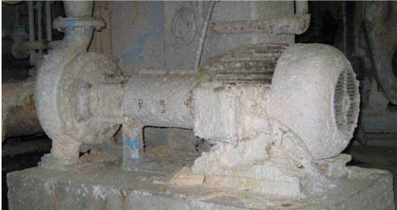
Example 1: Pump and motor coupling assembly in a paper mill.
This paper mill had an operator inspection system in place, which means that the operator should have checked it. I checked this unit intermittently throughout the week and it looked pretty much the same. Some issues should have come up immediately when an experienced inspector looked at this machine.
An experienced inspector would have noticed:
– I can’t see the cables very well, so I can’t check their condition.
– I cannot take the stroboscope to the connection because the inspection ports are covered.
– The motor runs hotter than necessary because it is covered with dirt.
– I can’t see the oil level in the pump.
– The pump’s drain plug is probably clogged.
– The breather tube is just a “goose neck” breather tube that is letting dirty air into the oil
– I wonder if the engine has jack bolts to allow for precise alignment?
– There is no flow meter or inlet or outlet pressure gauges on the pump, how would I know if it is running at the correct BEP?
– There are no locations or connections for vibration and temperature readings, I wonder where the previous guy took the readings so I could compare readings.
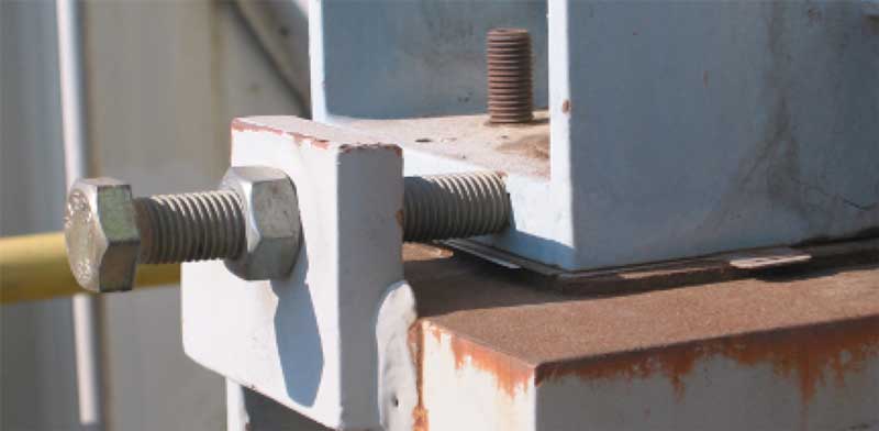
Example 2: Refinery engine lift bolt (push bolt).
Here’s a close-up of the lift bolt on the engine stand. What would an experienced inspector see? This photo was taken in the southern United States in March.
An experienced inspector would notice:
– The bolt is touching the chassis. As the climate warms, the bolt lengthens due to thermal expansion and pushes the engine off line. The bolt needs to be backed off.
– Great, there’s a jackbolt so we can align it well, but I wonder why they don’t buy them with the jackbolt originally, as it would be much cheaper than putting them in after installation?
Example 3: Solenoid valve in a food processing plant.
The picture shows a typical solenoid valve in a hydraulic system. An inexperienced inspector might just look at it and make sure that the valve is installed and that the electrical cable is intact.
An experienced inspector would do this:
– Measure the coil temperature, knowing that if the valve sticks internally, the coil will often heat up as it tries to move the stuck valve.
– Listen to the whirring sound of the solenoid. The whirring noise occurs when the solenoid tries to move the valve several times.
– Make sure there are no leaks, detecting leaks can cause performance problems and cause additional heat.
Example 4: Pneumatic regulator in a surface mine.
The picture illustrates a pneumatic regulator that has been in use for some time. Most inspectors would not look at the device at all because mechanics consider it part of instrumentation, while instrumentation technicians rarely do physical inspections of the equipment.
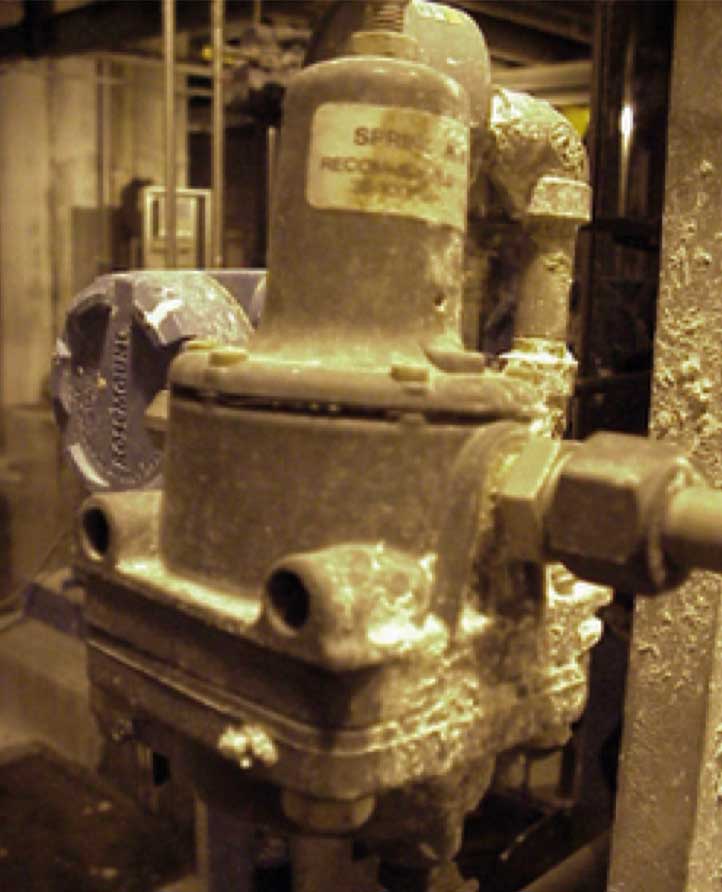
An experienced mechanic would:
– He would put his hand in front of the leak hole and check for air leaking from the leak hole. If he feels air, he knows that the membrane inside the device is broken.
These four simple examples are just to illustrate the difference between walking past equipment and understanding how to inspect it. As operations and maintenance managers, we should not just hand people a list of 40 equipment numbers and assume that they know and are prepared to inspect the equipment correctly.
Text: Torbjörn Idhammar, Managing Director, Idcon Inc | Images: Idcon, Shutterstock
Subscribe to the free Maintworld newsletter here!
Virtual Reality Brings Power to the Maintenance Business

Augmented reality is a viable new distribution channel for service instructions and enhances the product development process and service business of industrial companies.
Hanna Heinonen, responsible for technology and content development in product development and technical communication at Kone, has investigated in her doctoral thesis the opportunities offered by technical communication and augmented reality for industrial companies, especially in the context of the industrial service business. An essential part of her work includes the development of new distribution channels, especially for the needs of the service industry.
The study explored the potential of augmented reality to enhance the service business through both virtual reality (VR) and augmented reality (AR).
–More than 150 people from Kone’s global organization participated in the user testing of the study. The experts were receptive to the introduction of modern technologies into their daily work and estimated that they would make their work more efficient, says Hanna Heinonen.
Maintenance professionals often work in circumstances where the use of traditional guidance is difficult or impossible.
Maintenance professionals often work in circumstances where the use of traditional guidance is difficult or impossible. For example, changing a component often requires two hands, making it difficult to manage both paper and mobile instructions. In addition, protective gloves bring their own challenges to the table. It is also crucial that maintenance professionals have easy access to up-to-date information, preferably linked to the equipment being serviced. There is a demand for new distribution methods in the industrial maintenance sector.

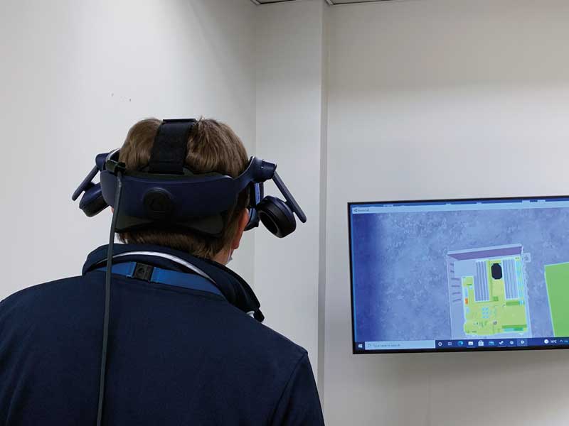
Virtual reality in product development
Until now, industrial companies have mainly used virtual reality for training purposes. Heinonen’s study focused on the use of virtual reality in product development in an industrial company, particularly in the process of creating service manuals. In collaborative VR, users in different physical locations work in the same virtual environment and see each other virtually face-to-face. They are in a virtual conference room together or meet on a virtual device. They can examine the device together, take it apart and reassemble it – in effect, acting as if they were physically in the same room.

– I found collaborative VR to be particularly effective for global and remote teams. It offers new opportunities to unify virtual teams by creating a sense of cohesion and enhancing internal communication compared to traditional communication tools, such as email or video conferencing. In addition, the use of virtual reality reduces the pressure for experts to travel within global companies and, of course, within Finland. Virtual reality also streamlines the process of creating and reviewing technical documentation at multiple stages, reducing both misunderstandings and iterations, thus making the product development process of industrial companies more efficient.
Until now, industrial companies have mainly used virtual reality for training purposes.
From paper manuals to smart glasses
Traditionally, user manuals are printed on paper. However, printed instructions in a toolbox or in the back of a van are not necessarily the most efficient way of doing things, because they are not always there when you need them, or they are not up to date. Manuals can even get lost, meaning that carefully guarded maintenance programs can fall into the hands of competitors. Many companies have therefore switched to online portals for distribution, making the instructions accessible from a phone, tablet, or other device. This means that maintenance professionals always have access to the right, up-to-date instructions. However, the use of mobile devices is not always easy when performing maintenance tasks, as often both hands of the maintenance technician are needed to complete the task.
The study looked at the use of smart glasses as a new distribution channel for service instructions. They free up the user’s hands to do the work, and in augmented reality, instructions can be followed in real-time as the maintenance task progresses, making work more efficient and reducing the chance of errors. With multi-channel distribution, the same information can be easily exported to different distribution channels, which in turn streamlines the process of publishing technical information and thus the product development process in companies.
The right level of information
– I based my research on the needs of the user and found that maintenance professionals have vastly different needs depending on their background and experience. The more experienced users need no more than a refresher, while the less experienced maintenance worker performing the same task naturally needs more guidance. The move to dynamic predictive maintenance programs also changes the situation, as each maintenance visit is different and even the more experienced maintainers need guidance on what to do with each piece of equipment.
It is important to be able to provide the right level of information for everyone, as too much explanation will frustrate the more experienced,while too little guidance will slow down newcomers and potentially cause incidents.
The introduction of augmented reality is part of a larger shift towards the use of the industrial metaverse in manufacturing companies.
– The study showed that new technologies allow us to provide everyone with the right amount of information from the same source material, making the job easier and at the same time more efficient. Feedback from users has been incredibly positive.
Promising hardware development
Smart glasses can be controlled by voice commands or hand gestures. Their use is not yet widespread in industrial maintenance due to the weight of the devices, their relatively short battery life, and their price. However, hardware development has been promising in recent years and it is quite possible to see a maintenance worker wearing smart glasses to perform tasks such as escalator maintenance in a shopping centre.
The remote monitoring of equipment and the data it generates will also make it easier to link instructions to the operating situation, providing more accurate information for maintenance professionals.
The introduction of augmented reality is part of a larger shift towards the use of the industrial metaverse in manufacturing companies.
Text KONE | Images: Kone, Freepik
Subscribe to the free Maintworld newsletter here!
How to Create Added Value with your EAM System
A well-stocked Enterprise Asset Management (EAM) system is invaluable for the maintenance department.
The possibilities of current EAM systems – which are called Next Gen EAM – are many. When they are used optimally and efficiently, they offer benefits that extend throughout the organisation.
Developers of EAM systems have not been idle in the past years. Thanks to Internet of Things, sensor technology and mobile maintenance, we can enrich the EAM system more easily and quickly with data about our assets. This makes the EAM system an important basis for further digitalisation, as shown by the ‘Digital Trends in Maintenance & Asset Management’ study that PwC and Mainnovation conducted in 2023.
Next Gen EAM
Next Gen EAM is surrounded by a range of applications with which a connection is possible, or of which part of the functionality is sometimes already built in. Think of Asset Investment Planning, Asset Performance Management, Business Intelligence, Predictive Maintenance, but also Mobile, GIS and BIM integration. Yet, an EAM system is mainly used by many companies as an electronic card index and digital work order system. While integration with other digital tools and applications can significantly increase operational efficiency, improve asset reliability, and deliver cost savings.
Efficient and optimal use of the EAM system is a prerequisite for continuous improvement.
Mobile Maintenance
Mobile Maintenance refers to the use of mobile devices, such as smartphones or tablets, to manage maintenance tasks and workflows in real-time. Usage leads to better efficiency and higher hands-on-tool time for technicians, and it allows companies to provide the information where it is needed, because the EMS system – and therefore all required asset information – is always at hand. The mobile application also boosts data quality through the mandatory input fields in the system. Due to the great ease of use, these fields are filled in quickly and easily so that the EAM system is enriched. Maintenance teams can quickly access the information they need to make well founded decisions, reducing downtime and improving the quality of maintenance activities.
Work order registration
The research ‘Digital Trends in Maintenance & Asset Management’, by PwC and Mainnovation, has shown that many companies have embraced mobile maintenance. The study also indicated what this technique is used for. The functionality that stands out the most is: work order registrations (70%). Technicians can easily prioritise tasks based on asset criticality and resource availability, leading to more efficient use of resources. In addition, companies also choose to use mobile devices for inspections (42%). The big advantage of a mobile device is that you can immediately take photos and upload them to the EAM system, on the spot.
Link with ERP
Packages from current developers of EAM systems often already have good integration with ERP. This integration enables seamless communication between departments, aligning maintenance activities with broader business objectives.
The middleware (the software between an operating system and the applications running on it) has been greatly improved and the integration options have been standardised. The most common interfaces with ERP are in the financial and logistics areas. These interfaces are fairly easy to realise. However, there is a pitfall that too much is ‘reprogrammed’, so that at some point the system can no longer process updates. This must be prevented by first standardising the processes across the systems and then the interface.
Predictive maintenance
We also increasingly see modern EAM systems integrated with data analysis tools and Internet of Things (IoT) sensors. Based on condition-based maintenance, the maintenance department can switch from reactive to predictive maintenance. Through real-time monitoring, EAM systems can predict when maintenance is needed, reducing unexpected failures and extending the life of assets. This predictive approach not only reduces maintenance costs, but also minimises downtime.
Improve continuously
Efficient and optimal use of the EAM system is a prerequisite for continuous improvement. This improvement process starts with defining the business processes in the field of maintenance and asset management. Which steps need to be completed and who is responsible for which step? This is supported by your IT landscape, where the EAM system takes a central role. The EAM system is enriched through careful registration. And based on the better data/content (also from PdM, LTAP, FMECA and PMO), you have powerful management information at your disposal to analyse deviations and achieve goals. If we constantly use this plan-do-check-act loop, we create a continuous improvement culture.
Text and images: Laura van der Linde, Mainnovation
Subscribe to the free Maintworld newsletter here!
A Beautiful Partnership: Maintenance Technicians and Artificial Intelligence

A fascinating future awaits maintenance technicians in the world of increasing access to artificial intelligence (AI), and other industry 4.0 digital advancements. A central question many industrial leaders are pondering […]
A fascinating future awaits maintenance technicians in the world of increasing access to artificial intelligence (AI), and other industry 4.0 digital advancements. A central question many industrial leaders are pondering is, “How will this technology shape our industrial world and the hands-on role of the maintenance technician?” We at Marshall Institute believe that a beautiful partnerships can exist between these technicians and AI. Admittedly, and understandably, past technological adoption and corporate initiatives have left many technicians wary of future advancements.
Our aim with this article is to illustrate several ways that partnership between techs and AI can lead to great outcomes. And in the process, we hope to allay concerns and boost excitement from technicians around the world.
Imagine the scene…you are a maintenance technician wearing your trusty toolbelt and armed with decades of hands-on experience. And, now, you have a new partner – AI. (Like ROBOCOP joining the Detroit Police Department.) It is not there to replace you or take over, instead it is the perfect supplement to your expertise. You are teaming up with a brilliant apprentice who can process data at lightning speed and make suggestions that might just save the day. How does that sound?
Farfetched? It might seem so, however, sci-fi fantasy is quickly becoming our industrial reality.
AI doesn’t steal your thunder; it enhances it! Instead of replacing your skills, it amplifies them.
We understand the hesitancy amongst technicians to adopt new digital tools. Change is awkward when slow, but downright terrifying when at the speed of light. Of course, there is the age-old, and justified, concern about technology taking jobs. And we have not forgotten the painful memories and legacy headaches of other failed ‘silver-bullet’ technologies and forgotten flavour of-the-month initiatives. History shows that technicians have good reason to recoil at the sounds of phrases like “digital plant”, “AI”, “game-changing technology”.
Let’s change the narrative and excite our technicians. The following examples are just some of the opportunities for great partnership and enhanced technical output.
Preventive Maintenance
I am sure that everyone reading this article has strategic asset management plans, existing PM programmes, and a robust RCM/PMO programme. [Spoiler Alert} This is not the ‘norm’. Many plants around the world have assets that have been bought cheaply, installed hastily, and commissioned before being correctly added to the CMMS, before parts are identified, before a PM programme has been built, and before techs have been trained, etc. Now imagine, for the average industrial site, a world where you no longer wait for things to break before you fix them. AI crunches and analyses historical and real-time data and predicts when a machine is likely to give you trouble. It is like having a sixth sense that tells you, “Hey, that conveyor belt is acting a bit funky. You might want to take a look at it,” allowing the technician to take action before disaster strikes, reducing downtime, and keeping operations humming along.
AI has the potential to greatly enhance a world-class manufacturing operation through its ability to add refinement and efficiency. By leveraging sophisticated algorithms and machine learning, AI can analyse vast amounts of data and constantly monitor and optimise processes. This can lead to improved productivity, reduced downtime, and enhanced quality control. AI-powered predictive maintenance systems can proactively identify potential equipment failures, enabling timely maintenance and preventing costly breakdowns. Additionally, AI can facilitate real-time inventory management, ensuring optimal stock levels and preventing stockouts or excess inventory. Overall, AI adds a layer of sophistication to manufacturing operations, enabling businesses to stay ahead of the competition and deliver consistent, high-quality products.
Troubleshooting
These days, at least in the U.S., good troubleshooters are in short supply! We have lost a lot of technical knowledge, and with it, troubleshooting capability. If this is the case for you too, imagine providing your apprentices, or less experienced technicians, with an AI tool that has access to a universe of technical manuals, past repair logs, and even real-time sensor data; it is like having a walking encyclopedia that whispers solutions in their ear. These techs will be backed by a digital brain that can analyse complex issues and recommend precise repairs at lightning speed.
AI crunches and analyzes historical and real-time data and predicts when a machine is likely to give you trouble.
AI doesn’t steal your thunder; it enhances it! Instead of replacing your skills, it amplifies them. It empowers you to make more informed decisions and tackle challenges that might have seemed impossible before.
Collaboration
Our belief is that the future is not just about machines and systems, it is about collaboration between people and tools, as it always has been. Imagine a scenario where a technician hits a roadblock when working on a complex piece of equipment. Instead of doing it alone, they can now tap into a global network of experts through AI-powered platforms. It is like having a team of colleagues at your fingertips, ready to jump in and lend their insights. They are no longer isolated in your workshop; they are part of a community of problem-solvers now, which they can both benefit from and contribute to!
Continuous Learning & Development
As this connected ecosystem of people, devices, and information matures, continuous learning becomes your superpower. Imagine if every solution you come up with and every tweak you make gets recorded and fed into the AI system. Human and AI partnership is like building a knowledge warehouse that never forgets, or requires coffee to remember. Over time, your AI companion learns from your experiences, and those of other technicians, becoming smarter and more capable with each issue it helps you solve.
The best organizations are world-class learners and people-developers. But we know that a commitment to developing people takes focus, time, and budget. As AI takes care of the repetitive and routine tasks, you will have more time to dive into advanced training and new technologies. It is like getting a chance to boost skills and become masters of their craft.
Closing Thoughts
Although my colleagues and I at Marshall Institute are optimistic about the future, I want to be clear that I am not suggesting that AI, and other Industry 4.0 tools, are standalone solutions to our reliability challenges. Tools do not create performance, they enhance it. So, it is our responsibility to ensure that the foundations of “asset management house” are sound before we build up. Part of this digital transformation is appropriately understanding the use and value of these tools and communicating their use and value to those most impacted. If we do this right, we can reduce fear, and maybe, just maybe, get technicians a little excited.
We believe that if we transition to the digital plant effectively, maintenance technicians will be stepping into a world where AI can be their trusted sidekick. It is a world of enhanced troubleshooting, predictive prowess, continuous learning, collaborative networks, and personal growth. The tools we use might be changing, but the heart of a technician – that unwavering dedication to keeping things running smoothly – remains at the centre of asset reliability.
Text: Alan Warmack, Director of Training Services – Marshall Institute, Inc. | Image: Freepik
Subscribe to the free Maintworld newsletter here!
Case Study: Slow-Speed Bearing on Oven Motor – Failure Detection using Ultrasound
Vibration analysis has long been the instrument of choice for the inspection of bearings and other rotating equipment. And more commonly, vibration analysis is being used in conjunction with ultrasound.
Because of the versatility of ultrasound, if a facility does not have a robust vibration analysis program in place, then ultrasound can be implemented not only to detect early stage bearing failures, but also to detect a number of other issues. If the vibration analysis is performed by an outside service provider on a quarterly or monthly basis, ultrasound can be used during the interim.
This will help the facility to know the condition of some of the more critical assets prior to the service provider entering the facility; therefore, the service provider’s time can be used more efficiently because the plant knows if there are any prominent problems with the assets that are being monitored by ultrasound. The service provider can then prioritise based on the ultrasound findings.
Another scenario in which ultrasound may first be used over vibration analysis is with the monitoring of slow-speed bearings. The monitoring of slow-speed bearings with ultrasound is easier than you might think. Since most high-end ultrasound instruments have a wide sensitivity range and frequency tuning, it is possible to listen to the acoustic quality of the bearing, especially at slower speeds. In extreme slow-speed bearing applications (usually less than 25rpm), the bearing will produce little to no ultrasonic noise.
In that case, it is important not only to listen to the sound of the bearing, but more importantly to analyse the recorded ultrasound sound file in spectrum analysis software, focusing on the time wave form to see if there are any anomalies present.
If “crackling” or “popping” sounds are present, then there is some indication of a deformity occurring. In bearing speeds above 25rpm, it is possible to set a baseline decibel level and trend the associated decibel level readings over time.
Using Ultrasound to Identify Oven Motor Bearing Failure
An inspection with an ultrasound instrument was carried out on a site with a newly-installed oven dryer. This was a large drum oven, about 20 meters long by 5 meters wide. It was rotated by 4 large motors, each of them having two large sets of bearings. These motors rotate the oven at a speed of around 7-10 rpm. Here we are talking about a case of extreme slow-speed bearings, which is usually a challenge to inspect.
The monitoring of slow-speed bearings with ultrasound is easier than you might think.
An ultrasonic instrument was used to inspect all bearings – almost all of them presented a nice and smooth sound and a 0dB reading, except for one. On one of the bearings from this set, the ultrasonic instrument was displaying 2dB instead of 0. Also, the sound heard from the headphones was different: it was not smooth as in the other bearings and it presented a repetitive “knocking” sound. This gave the inspector an indication that something might have been wrong with this specific bearing.
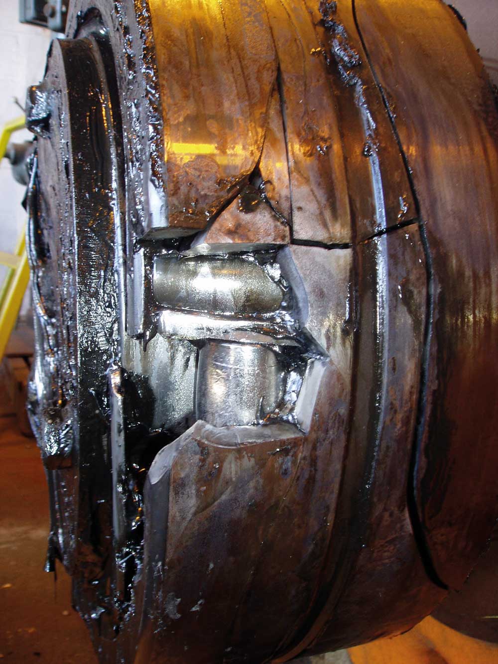
– in which case the grease sample would show metal contamination. The results from the grease analysis indeed showed the presence of metal particles, confirming damage as indicated by the ultrasound instrument.
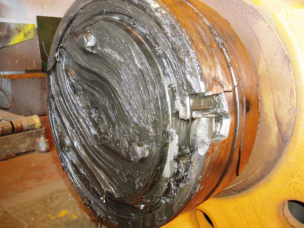
The next step was naturally to schedule an outage to replace the bearing which, as can be seen in the images below, was in very bad condition. Part of the outer race came away as it was opened. It was also noticeable that one of the rollers had moved 90 degrees. The cage had been totally damaged too.
If “crackling” or “popping” sounds are present, then there is some indication of a deformity occurring.
Ultrasound and Slow-speed Bearings – the Method
As we can see, ultrasound technology is very useful when trying to monitor the condition of slow-speed bearings, and an ultrasonic instrument/sensor is able to provide maintenance personnel with a warning of failure, even at extreme slow speeds like in this case.
With bearings rotating at normal speeds, ultrasonic inspection can be performed by comparing changes in dB values; bearings that are found to have a value above a decibel baseline will need lubrication, or may already be in a state of failure, depending on how many decibels the value is above the baseline.
However, with slow-speed bearings, comparing dB levels and establishing alarms is not enough: in many situations the difference in the dB levels will not be significant or may even be non-existent, in which case the inspector might think there is nothing wrong with it.
For slow-speed bearings, one must rely on the sound quality and the sound pattern. For this, it is necessary to use an ultrasonic instrument with sound recording capabilities, like the Ultraprobe 15000, and then analyse the sound file on sound spectrum analysis software like the Spectralyzer from UE Systems. Maintenance professionals can then simply record the sound produced by a slow-speed bearing, load the file in Spectralyzer and analyse it in the Time Series view.
For slow-speed bearings, one must rely on the sound quality and the sound pattern.
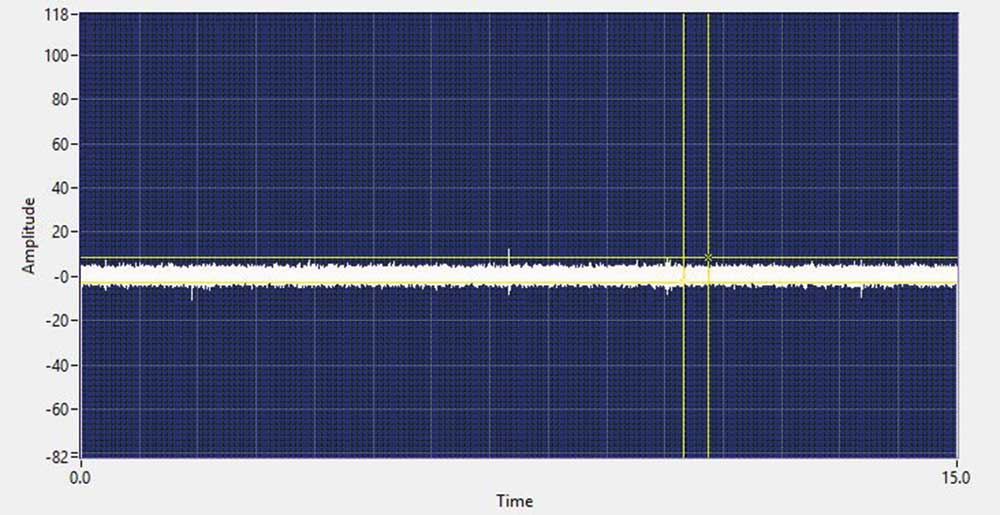
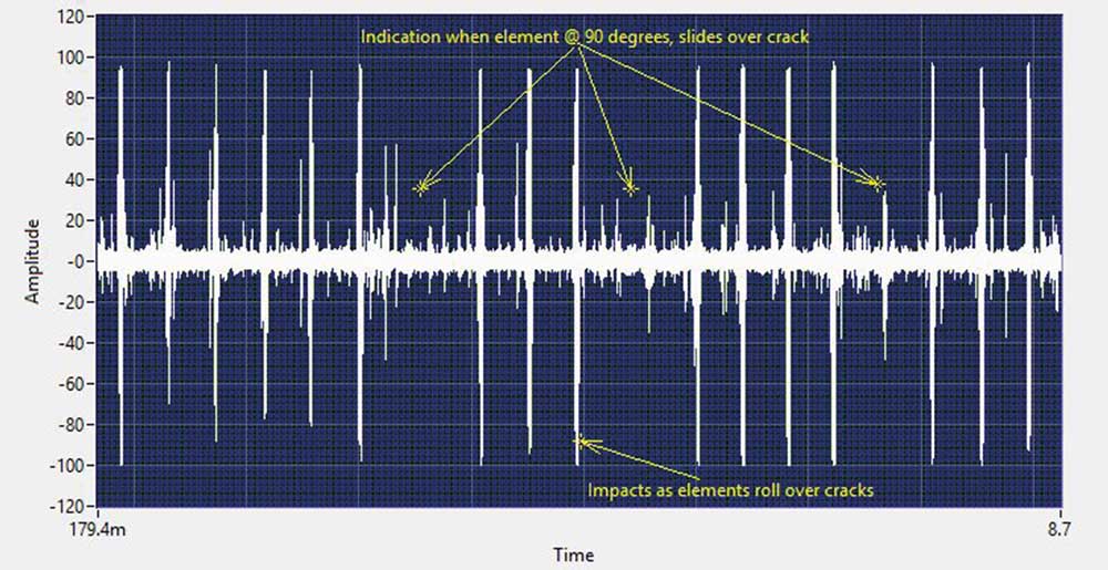
The spectrum analysis
The spectrum analysis of this oven motor bearing shows clearly where the roller at 90 degrees hits the crack as the knock stops briefly. Thus, the sound pattern indicates an already existing problem, being the most reliable source of information when determining the condition of a slow-speed bearing using ultrasound.
On the other hand, the spectrum of a recorded sound from one of the “good” bearings shows a very different picture: a very uniform spectrum with almost no changes in amplitude.
This find has saved the company a significant amount of money, as it was necessary to get cranes in to replace such a big bearing, a job that took up to 6 hours. Luckily this was done during a planned outage, avoiding the costs of unplanned downtime.
Text:Christopher Hallum, Operations Manager | Images: Ultra Systems
Subscribe to the free Maintworld newsletter here!
Moving Massive Loads with Half-Millimetre Precision – Remote Handling Solves a crucial maintenance need for fusion reactors

Worn parts need to be replaced and nuclear dust needs to be removed and handled safely. The remote replacement of massive divertor cassettes in the ITER reactor was demonstrated at the beginning of the year on the DTP2 test platform at the VTT Technical Research Centre of Finland.
In the ITER reactor in southern France, the world’s largest fusion reactor experiment, the hydrogen isotopes deuterium and tritium fuse at high temperatures to produce superheated plasma. Strong superconducting magnets confine the plasma in a donut-shaped tokamak chamber.
Although ITER is not designed to produce electricity, it paves the way for reactors that can produce electricity. Fusion releases a lot of energy in the form of fast neutrons and charged particles, which heats the plasma. The cladding of the reactor wall traps heat, making it easier to generate steam to power turbines to generate electricity.
Extreme temperatures
Although plasma is ten times hotter than the sun, superconductors require temperatures close to absolute zero to operate.
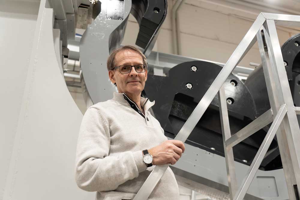
“This contrast perfectly illustrates the extreme conditions that place special demands on the operation of a fusion power plant. One of the biggest challenges is maintenance, and this is where the Tampere Divertor test platform 2 comes in handy,” says Jarmo Alanen, Senior Researcher at VTT.
Future fusion reactors will also feature mega-scale components and fine-tuned, sensitive technology.
“The good news is that fusion plant elements and nuclear waste will only remain low-level radioactive for about 100-200 years, while fission fuel will remain radioactive for 100 000 years. But of course, during the life of the plant, we will still have to play with highly radioactive particles and elements to keep the plant running,” Alanen explains.
The result of years of development
Fusion for Energy, VTT Technical Research Centre of Finland and the University of Tampere have been working together for more than ten years to develop and integrate ITER’s remote processing control system into the DTP2 test platform.
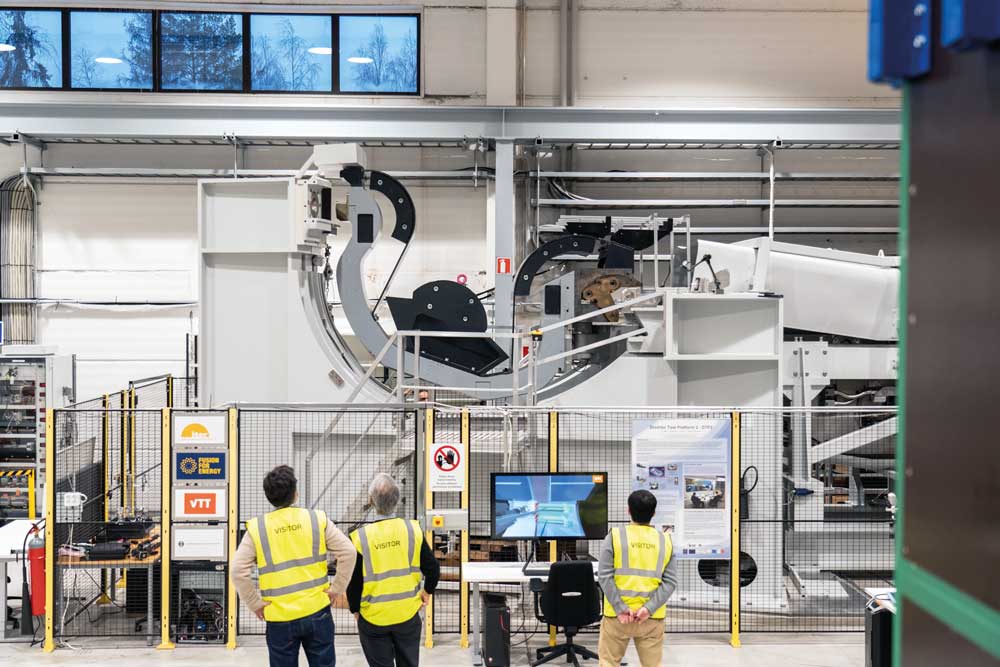
VTT hosts the Divertor Test Platform (DTP2), which includes a control room, dedicated remote handling equipment and a full-scale prototype of the ITER Divertor Cassette, weighing about 10 tonnes, 3.5 m long and 2.5 m high. ITER will have 54 such cassettes that will form a divertor, a massive “ashtray” into which most of the plasma impurities will fall. Removing a heavy cartridge requires a robot of the same weight to move through a narrow maintenance tunnel.
The project has been a successful partnership between applied science and industry: VTT developed a virtual 3D environment and a remote diagnostics application, complemented by a GTD Command and Control application, Genrobot robotics software and an LLC communications driver.
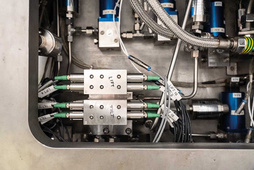
Digital hydraulic valves
The use of digital hydraulic valves for remote operation has also been a game changer in ensuring a more accurate and reliable system operation.
Because fusion reactors are sensitive to contaminants, the remote system uses water-based hydraulics. The digital valve, DigiValve, is an innovation of Tampere University of Technology, Fluiconnecto and Tamlink, which promises increased reliability in demanding environments.
“The servo valves originally used in the remote handling system turned out to be less than ideal, as they wore out easily and were prone to clogging. DigiValves is much more fault- tolerant, as the system with 16 on/off valves is not dependent on just one valve as in the old solution. They are easy to control digitally and offer better performance and very accurate control,” says Alanen.
3DNode camera-based monitoring system
Another innovation, the 3DNode camera-based tracking system, measures the coordinates and rotation angles of the cassette from markers placed in the service tunnel and cassette to calculate the robot’s pose.
Commercial machine vision solutions exist, but none of them meet the limitations of ITER, such as material properties and the low resolution of radiation hard cameras.
Successful demonstration
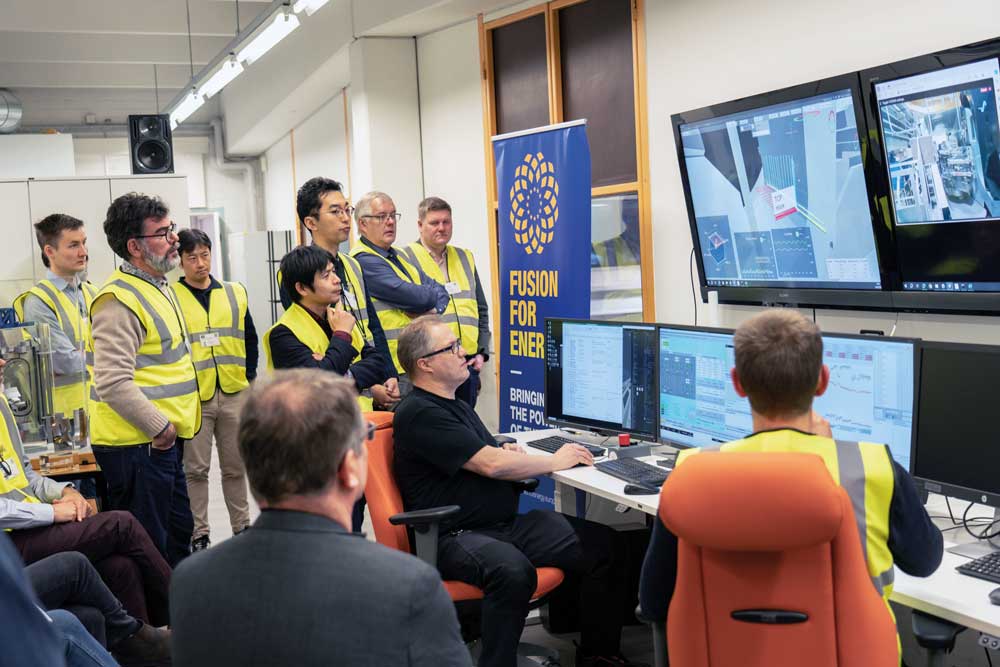
How would the valves and software work together in full operation? At the beginning of the year, F4E and VTT invited representatives from their subcontractor, the ITER Organisation, and the ITER domestic agencies in Japan and Korea to participate in a demonstration of the system at DTP2 at VTT.
The divertor cassette was carefully transported throughout its journey. The entire remote handling system worked flawlessly without any disruptions.
The cartridge exchange operation was carried out using the ITER compliant remote handling control system implemented by Genrobot and other control system elements mentioned above.
“Although the user can more or less rely on pre-learned motion paths, the operator may need to manually control the robot. Sometimes small movements are needed, especially because of the tight fit of the robot-cartridge interface or to compensate for deflections when lowering a 10-tonne load. The required simultaneous lateral movement and rotation, millimetre by millimetre, without a camera view, is quite a task. The virtual reality model and virtual instruments provided by C&C are crucial,” says Alanen.
“DTP2 provides an excellent environment for testing and preparing remote handling systems for ITER’s first assembly phase. Work can now begin on new versions of GENROBOT, which aim to simplify and optimise operations,” says Emilio Ruiz Morales, F4E’s Remote Management Manager, who led the engineering team developing the software.
New commercial opportunities
According to Alanen, these innovations are a good example of applied science and industry working together to create solutions with wider commercial potential. The fusion reactor is probably the most demanding environment in water hydraulics, but the same technology could be used in other industries that need to move large masses with high precision.
“Construction, manufacturing and transportation are just a few examples of industries that could benefit from solutions developed for ITER’s remote handling needs,” says Alanen.
“The European-funded work has paid off and can be applied beyond fusion,” explains Salvador Esque, F4E’s Remote Control Officer, who is responsible for the progress of this device.
“In this technology sector, we have invested in people to acquire new skills and deepen their expertise by developing and validating new technologies. We have funded a test facility that has become a centre of excellence in this field, which can be used for real remote processing operations in ITER. With F4E’s participation in this project, we are strengthening European leadership,” says Carlo Damiani, Programme Manager for Remote Processing at F4E
Robots for other maintenance tasks
Of course, handling divertor cartridges is not the only task in fusion reactor maintenance. But the conditions are often dangerous and out of reach of humans. Alanen and his team are currently investigating a range of smaller robots that weld, vacuum, tighten bolts and open or close doors inside a radioactive reactor. Many of the tasks are delicate in nature, and excessive use of force can have serious consequences.
“The haptic controller gives the user tactile sensations of what the robot they are controlling is doing. While automation increases efficiency, some tasks still require a human operator. Robotics can be of great help in extending the range of possible activities and increasing the safety of maintenance,” says Hannu Saarinen, senior researcher at VTT.
F4E-GRT-0901 Project Facts
• The project has received EU funding via Fusion for Energy (F4E), the organisation managing Europe’s contribution to ITER, plus contributions from VTT and Tampere University.
• The Project has been coordinated by VTT.
• The main milestone of F4E-GRT-0901 was the demonstration of the ITER Remote Handling Control System at F4E Divertor Test Platform (DTP2) hosted by VTT in Tampere, Finland.
• Under the grant, VTT has provided the Remote Diagnostics Application and Virtual Reality, and Tampere University the 3DNode camera-based pose measurement system.
• GTD, Tamlink and Fluiconnecto have also contributed to this area of work via other contracts signed by F4E; GTD with Genrobot, Command & Control, and LLC communications software; Tamlink and Fluiconnecto with DigiValve water hydraulic digital valve. These all together with VTT and Tampere University contributions were experimentally validated under F4E-GRT-0901 at DTP2.
• F4E has carried out the technical coordination between F4E-GRT-0901 and the other contracts.
Sources: VTT and F4E
Subscribe to the free Maintworld newsletter here!
Can 3D-Printed and Laser-Hardened Tools meet the Strict Requirements of Production?

SSAB has tested 3D printing in the production of hard-to-find spare parts. The results showed a longer lifespan of parts and lower costs.
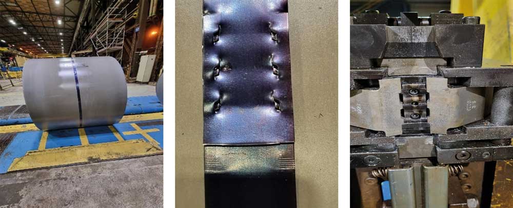
At SSAB’s Borlänge operations, Signode belts are used to prevent the unwinding of coils and ensure safe transport. The straps are held place by a stamping function that locks the ends of the strap together.
Some of the tire machines in use are old and acquiring spare parts from the supplier became difficult to impossible. A solution to the problem had to be found, prompting the maintenance department to look for new supply chains for spare parts. It was decided at this point to test an alternative method that can be used to quickly produce parts – 3D printing.
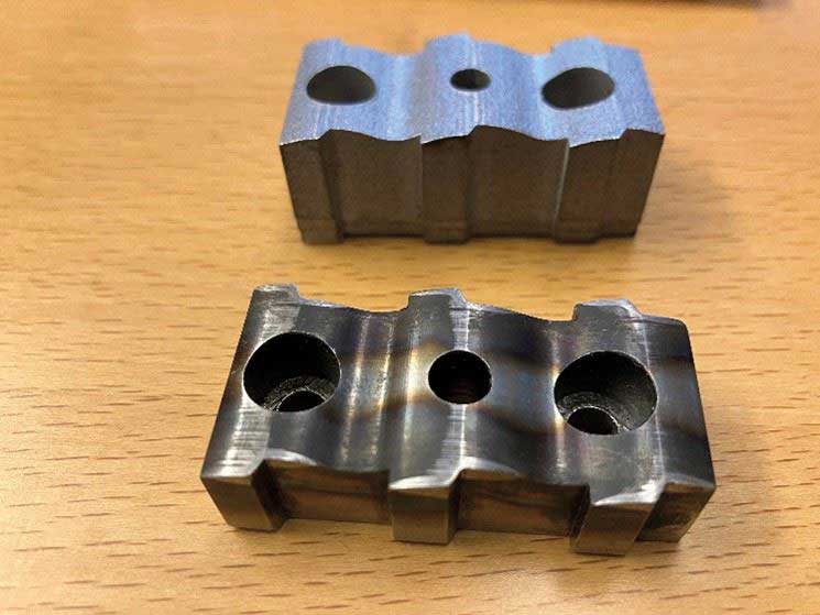
The stamp blanks were produced by 3D printing at SSAB in Oxelösund, Sweden. After printing, the stamps were processed to the final tolerance and sent for laser hardening of the wear surfaces.
“3D printing together with SSAB TS2 powder produces a material that is both hard and tough, and with laser hardening of the material, we have obtained a product that has performed beyond expectations,” says Jesper Vang, Director of Powder Technology at SSAB.
Promising results
Laser hardening is based on heating the surface with the energy of the laser beam and then cooling it quickly, i.e. cooling it with the surrounding material. The main advantage of laser hardening is that only the surface that needs more hardness is hardened, which gives low energy consumption and thus minimal distortions.
Laser-hardened 3D-printed stamps were found to have a lifespan three times longer than previously-used stamps. In addition to a better service life, manufacturing costs are also significantly lower.
“We are currently looking for more components for SSAB’s various facilities, where the advantages of 3D printing and laser hardening can be utilized.”
Emission-free steel powder
Steel production is a significant source of carbon dioxide emissions in the 3D printing of steel products. SSAB has recently launched the world’s first emission-free steel powder, which has already been delivered to some customers. Last year, 3 HT
Laser 3D-printed the first fossil-free steel component suitable for a forest machine”The strong steel components of 3D printing help reduce the amount and weight of the raw material used and increase the functionality of the final product. This is especially important in weight-saving industries such as the automotive industry or heavy machinery. It increases performance and reduces their CO2 footprint,” says Jesper Vang.
SSAB Zero® is steel made from recycled scrap using fossil-free energy sources, resulting in virtually zero emissions from the steelmaking process.
3D printing market size and trends
The global 3D printing market size was estimated at USD 20.37 billion in 2023 and is expected to register a CAGR of 23.5% during 2024-2030. Aggressive research and development of 3D printing and growing demand for prototyping applications in various industries, especially healthcare, automotive, and aerospace and defence, are expected to drive market growth.
The industrial printer segment was the market leader, accounting for more than 76.0% of global revenue in 2023. There is now a growing demand in industry for 3D printing, due mainly to its widespread use in prototyping, design and tooling. As a result, the industrial printer segment is expected to continue to dominate during the forecast period.
The metal segment was the market leader in 3D printing and accounted for more than 54% of the global turnover in 2023. Moreover, the metal segment is expected to maintain its leading position during the forecast period and grow at the highest CAGR for the year. over. 28% in 2024-2030.
Source: Grand View Research.
Text and images: SSAB
Subscribe to the free Maintworld newsletter here!
Selecting the Correct Bearing Seal
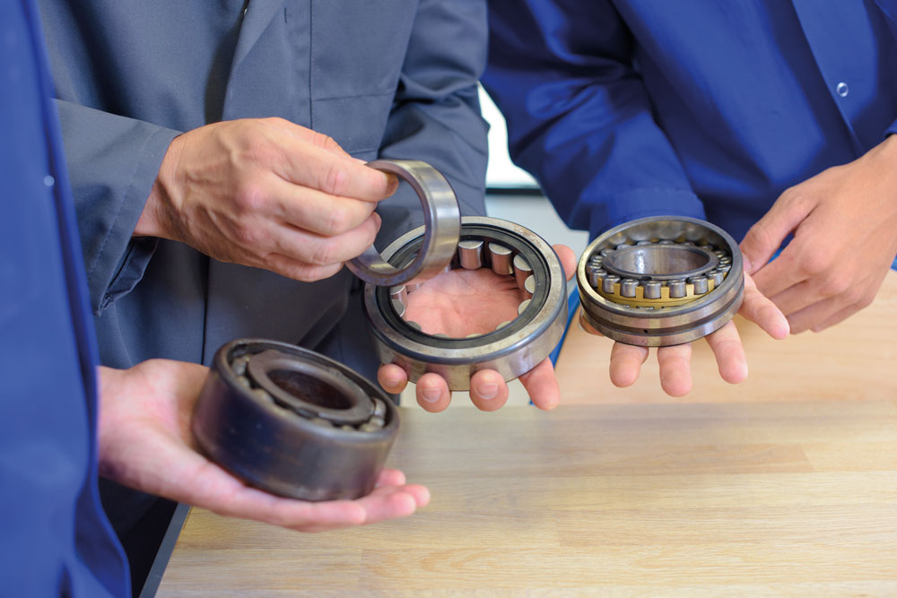
Seals keep lubricant in the bearing and bearing chamber, and exclude contaminants.
The primary functions of a bearing seal are to keep lubricant in the bearing and bearing chamber and to exclude contaminants. Some seals are integral to the bearing; others aren’t. The focus here is on what to consider when selecting external bearing seals.
Key factors for selecting the right bearing seal for an application typically include:
• Bearing type (rolling or sleeve)
• Lubricant (oil or grease)
• Seal friction and consequent heating
• Shaft surface speed and finish
• Physical space available
To select the appropriate seal for a given application, match the relevant factors from the above list with the characteristics of the following external seal types.
Common types of external seals
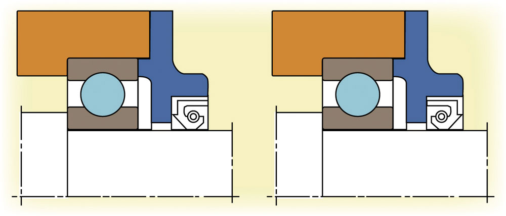
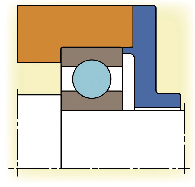
The types of seals most commonly used with rolling (ball and roller) bearings are contact or lip seals (Figure 1), non-contact seals (Figure 2), and to a much lesser degree various kinds of bearing isolators (Figures 3, 4 and 5) that combine the functions of contact and non-contact seals in different ways. The labyrinth seal (Figure 6) is a non-contacting seal that’s normally used with sleeve bearings.
Contact seals. Contact seals form an effective sealed interface by applying continuous pressure to the shaft surface with a resilient material. These seals make it difficult for fluids or solids particles to penetrate the sealed area, but direct contact with the shaft creates friction and heat that can degrade the seal and damage the shaft’s surface finish. If a less effective sealing method is acceptable, an alternative is a non-contact seal.
Non-contact seals. Non-contact seals produce much less friction (if any) and heating than contact seals. Unfortunately, they also allow lubricant to leak out of the bearing chamber and liquid or physically small contaminants to enter.
Bearing isolator seals. Bearing isolators combine the characteristics of contact and noncontact seals in a single unit but use the contact features to “drive” part of the seal at the shaft’s rotating speed. Such seals afford more protection than individual contact or non-contact seals.
They also can be used with either grease or oil lubrication, and with sleeve or rolling bearings.
Although bearing isolators are more costly and require more physical space than contact or noncontact seals, they deliver more effective sealing.
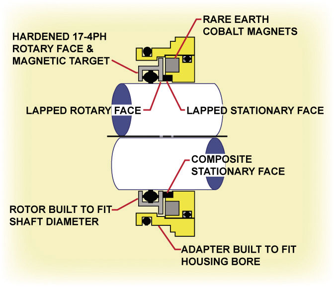
• Contacting isolators. The first bearing isolators were non-contact labyrinth seals that greatly reduced contamination ingress but didn’t stop moisture or other vapors. A newer version called a contacting isolator (Figure 4) uses rare-earth magnets to apply tension to lapped contacting faces, just like a mechanical pump seal. Although contacting isolators stop all solid and vapor contamination, they have surface speed limitations–a maximum of about a 4″ (100 mm) shaft at 3600 rpm.
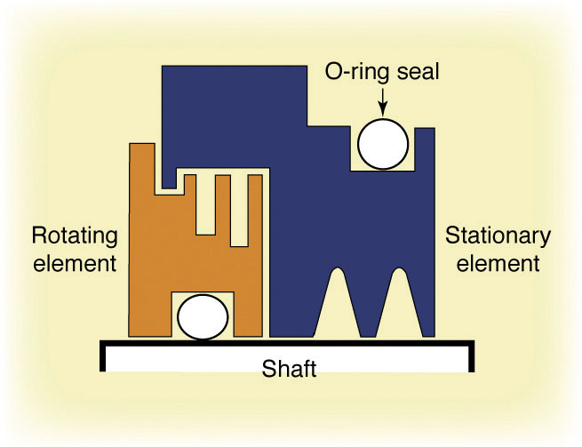
• Labyrinth-design isolators. Another variation of the bearing isolator has a labyrinth design and an O-ring or other elastomer element that keeps the labyrinth channel closed when the shaft is stopped and expands by centrifugal force to open the channel when the shaft is rotating. This prevents vapor ingress while the machine is off and eliminates friction/heat when it’s running. Special long-relief isolators are used in sleeve bearing applications to accommodate the bearing’s axial end float.
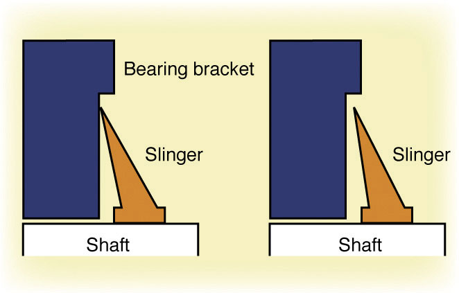
• Shaft slingers. These seals combine elements of contact and non-contact seals (Figure 5). Shaft slingers make contact with the end bracket while the machine is idle and move away from it (by centrifugal force) when the shaft is rotating.
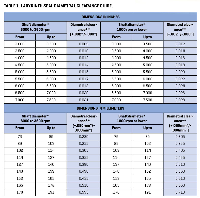
Labyrinth seals. Another type of non-contact seal in common use is the labyrinth seal (Figure 6). Labyrinth seals can be used with rolling or sleeve bearings, and with oil or grease lubrication. Suggested clearances for labyrinth seals with oil-lubricated sleeve bearings are given in Table 1.
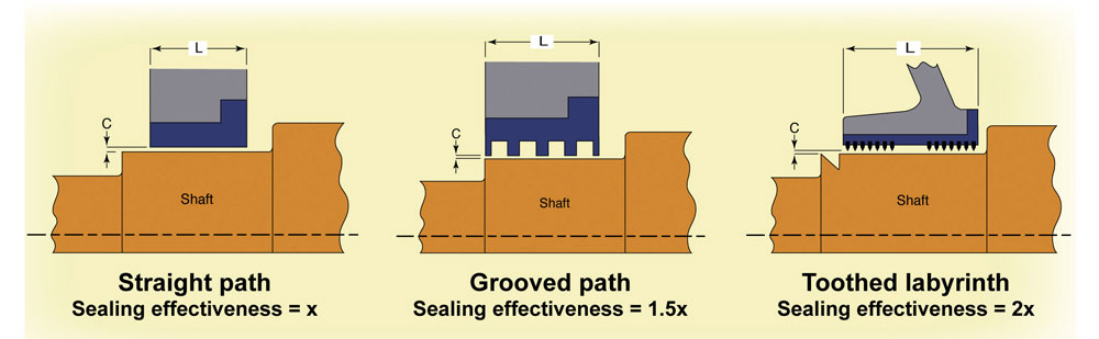
Suggested diametral clearances for labyrinth seals with grease-lubricated rolling bearings are 4-8 mils per inch (0.04-0.08 mm/cm) for shaft diameters below 2” (50 mm), and 5-10 mils per inch (0.05- 0.10 mm/ cm) for shafts 2” (50 mm) and larger.
Seal selection
Contact seals or bearing isolators are good choices for most oil-lubricated bearings, with the major exception of sleeve bearings for which labyrinth seals are commonly used. Non-contact seals aren’t acceptable in most oil-lubricated applications because they allow leakage.
The options for grease-lubricated bearings run the gamut, from non-contact and contact seals to various kinds of bearing isolators and labyrinth seals. (Note that virtually all sleeve bearings are oil lubricated, whereas most rolling element bearings are grease lubricated.)
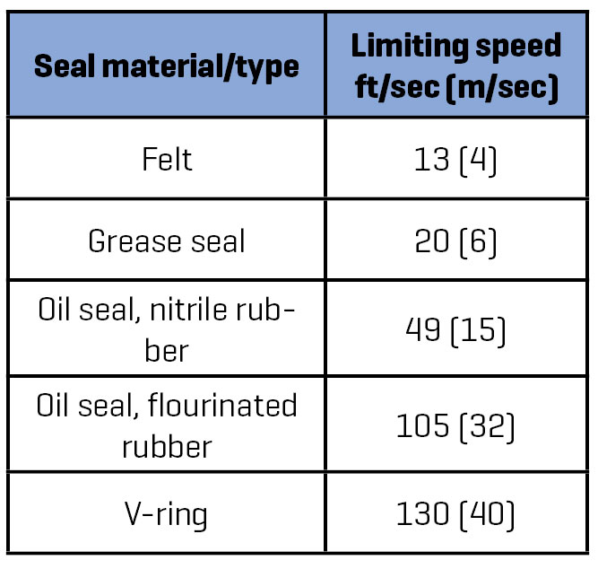
Shaft surface speed is always a consideration for contact seals. If it’s excessive, overheating from friction will degrade the seal material and possibly damage the shaft surface. Table 2 provides limiting speeds for some common contact seal materials.
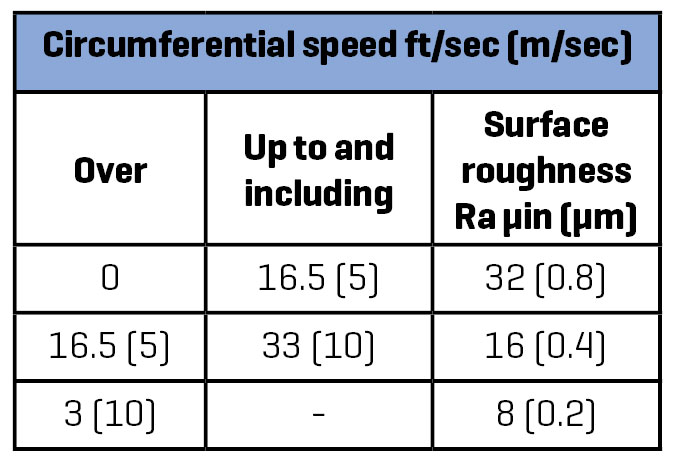
Contact seal friction and wear are also affected by shaft’s surface finish. Suggested shaftsurface finish tolerances are given in Table 3.
Thomas Bishop, P.E., is a senior technical support specialist at the Electrical Apparatus Service

Association (EASA), St. Louis, MO; 314-993-2220; 314-993-1269 (fax); easainfo@easa.com.
EASA is an international trade association of more than 1,700 firms in nearly 70 countries that sell and service electrical, electronic, and mechanical apparatus. For more information, visit www.easa.com.
Images: EASA and SHUTTERSTOCK
Subscribe to the free Maintworld newsletter here!
IT Asset Management Software Market Size is Set to Grow by USD 456.14 Million from 2024-2028

According to Technavio, the global IT asset management software market size is estimated to grow by $456.14 million between 2024 and 2028, growing at a CAGR of nearly 7.58% during the forecast period.
SMEs and large enterprises are leveraging ITAM software to optimize hardware and software inventories, streamline asset acquisition, and reduce asset acquisition costs. ITAM solutions provide real-time access to critical information, facilitating informed procurement decisions and eliminating duplicate purchases.
Key features include licensing management, software discovery, optimisation, measurement and centralisation of information security. The cloud sector, including SaaS applications, is a major driver of growth in the ITAM market, with VMware, CEOs and hybrid cloud solutions also playing a significant role. The aerospace and defence, IT and telecom industries are also investing in ITAM solutions to improve asset utilisation and cost savings.
The IT asset management software market is growing, but choosing the optimal solution remains a major challenge for organisations. Failure to understand business needs and software capabilities can lead to inefficient deployments. Integration problems result from a lack of expertise in customising asset management software, which hampers market expansion.
Key trends include cost considerations, security issues, centralisation, automation, IT infrastructure, cloud solutions and regulatory compliance. Compliance is a particular concern in the first quarter of the forecast period as large enterprises in the large enterprise sector, such as manufacturing, healthcare, finance, government, telecoms, retail, technology, energy, transport and education, seek to optimise their IT asset management. Cloud-based improvements such as software discovery, optimization, metering and licensing management are essential to managing complex IT infrastructures. In addition, hardware components and procurement decisions in the manufacturing industry require closure and financial market considerations.
Subscribe to the free Maintworld newsletter here!
Latest