Aircraft Reliability Programme
The reliability programme of aircraft in operation and maintenance is a combination of statistic monitoring and recording of the events associated with the airworthiness of an aircraft. The results obtained by monitoring reliability in operation may serve as a basis for supplementing or modifying the aircraft maintenance programme; such changes would indicate the malfunction of components or systems manifesting lacks and the need for early control, or replacement during utilization.
On the basis of the reports on reliability monitoring of air carriers’ maintenance services, the aircraft manufacturer collects and analyses the data for a large number of aircraft, thus being able to establish which are the systems and respectively components of the aircraft that cause problems in aircraft operation in most cases. In this article the methodology of calculating the indicators of reliability monitoring is described and the results of reliability monitoring presented on the example of one type of aircraft.
In the aircraft industry maintenance is considered to be one of the key segments in the business successfulness of an air carrier. By this, efforts are made to achieve maximal aircraft utilization with a security level as high as possible and minimal operative and ecological costs. As a result, aiming to increase profitability, and monitoring the reliability of an aircraft, its components and systems is of great benefit to aircraft carriers.
The primary purpose of any aircraft reliability programme is the collection of data and information and their statistic analysis to get valuable feedback with the data on irregularities developed in operation for an air carrier and a manufacturer. The programme of reliability monitoring serves as a supplement to the standard maintenance programme of a particular aircraft in order to maintain its continuous airworthiness.
In the first part of the article the methodology of calculating the parameters for aircraft reliability monitoring in operation and the interpretation of monitoring results are presented. Further on, a report of the manufacturer of one aircraft type is given, together with the presentation of the components with the highest number of unscheduled removals on the aircraft. At the end some concluding remarks are brought.
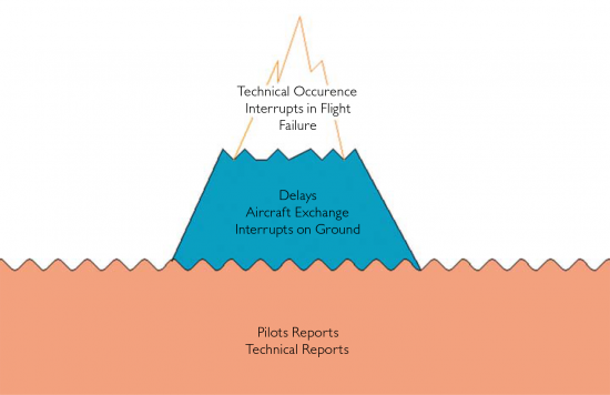
Figure 1. The “Iceberg” of parameters for monitoring aircraft reliability. Source: Airbus Customer Services: Reliability Control Program Training.
Parameters for Monitoring Aircraft Reliability in Exploitation
For monitoring the aircraft reliability technical data obtained in operation as well as regular and extra inspections of an aircraft, its systems and components are evidenced. The data collected in that way are the basis for each reliability monitoring and the conclusions obtained and based on them depend on their accuracy and so the total result. The obligation of collecting the data lies on the air carrier according to the requirements of aviation regulations for keeping continuous airworthiness of aircrafts EASA PART M*, item M.A.302 (d) and acceptable ways of meeting the requirements AMC** M.A.708 (c). The parameters monitored for aircraft reliability in operation are the following:
- flight hours
- flight cycles
- technical delays
- technical cancellation
- pilot reports
- technical staff reports
- unscheduled component removals
- component removals
- in-flight shut down
- unscheduled engine removals
- shop visits.
To facilitate comparisons between air carriers for the same type of aircraft the reliability indicators may be classified in four main groups:
- general aircraft reliability indicators
- structure reliability indicators
- aircraft components reliability indicators
- power plant reliability indicators.
After collecting the data for a given month, they are statistically analysed and the data of aircraft availability and reliability obtained. The parameters are to be monitored as a large whole, so that the reliability programme would be as effective as possible. This may be well illustrated by an “iceberg”, Figure 1.
In Figure 1 it is evident that the reports and complaints (of pilot/technical staff) themselves do not indicate which problem has the largest effect on aircraft operations and that operative interruptions (technical occurrence, interrupts in flight, failures) show only the tip of the “iceberg” and not the cause of the problem.
Interpretation of the Results of Reliability Monitoring
When all the data for a given month are collected, calculations follow showing the reliability level of the aircraft, its components and systems. The systems and the components of an aircraft are classified according to ATA-100 specification, which is a standard documentation for all commercial aircraft. According to ATA-100 specification, an aircraft is divided into systems and subsystems. The systems are constituted of a power plant, structure, electric systems and similar. Subsystems include particular parts, which together make one system. They are all specified by a multi-digit ATA number, where the subsystems of one system have the same two digits as the ATA number of the system they form.
Aircraft Availability
For aircraft availability assessment as an indicator “an average number of available aircraft of a fleet in an observed period” is usually used. The observation period of one month is considered. The aim is to get the data on the average number of available aircraft in the period observed. The total possible capacity of the fleet of one aircraft type expressed in hours is:
huk = hm ⋅ iuk (1)
where:
hm – is the number of hours in the period observed, e.g. one month
iuk – is the total number of aircraft of the observed type.
Due to maintenance, the aircraft were not operatively available for hs hours, and available for use uk s h = h − h hours, respectively. Accordingly, the number of available aircraft during the observed period of time equals:
ia = huk - hs / huk x iuk (2)
Aircraft Despatch Reliability
Aircraft despatch reliability is the probability that the aircraft will take off on scheduled time. Here the delays occurred due only to technical reasons, i.e. due to carrying out maintenance services are considered. The despatch reliability is defined by:
Rd = 1 - nd + nc / n (3)
where:
nd – is the number of delays in the observed period being larger than some default time due to technical reasons (5 to 15 minutes)
nc – is the number of flight cancellations due to technical reasons
n – is the total number of cycles (of takeoffs) in the observed period.
As an indicator, instead of “despatch reliability”, “despatch reliability rate” is usually which expresses the despatch reliability in percentages. This may also be interpreted as an indicator of successful aircraft despatches in relation to a hundred take-offs.
Aircraft System Reliability
Aircraft systems are monitored according to ATA 100 specification. To assess reliability the malfunction of particular aircraft systems is monitored, due to which some components are to be removed in an unscheduled manner. Also in this case this indicator is in practice presented in somehow modified form and called “the system reliability rate”, and it shows an average number of unscheduled removals of particular components of a system to a thousand hours of flight.
iur = nur / nks ⋅ h x 1000 (4)
where:
nur – is the total number of unscheduled component removals in the observed period nks – is the number of components in a system h – is the total aircraft flight hours in the observed period.
Number of Pilots and Technical Staff Reports
Reliability indicators may be defined on the basis of pilot reports or on the basis of observations of technical staff. For example, “the level of reliability on the basis of pilot reports in the observed period in relation to a hundred take-offs” can be defined:
ip = np / nto x 100 (5)
where:
np – is the number of pilot reports in the observed period
nTO – is the number of take-offs – number or cycles in the observed period.
Indicators of Structural Reliability
Aircraft structural reliability is obtained by the methods of non-destructive testing – NDT. Structural health monitoring – SHM represents a concept of a system for continuous monitoring technical health of aircraft structure. The basic principle is the creation of reliable non-destructive technology, which would be an integral part of aircraft structure. Sensors would be built into the aircraft to detect failure (material fatigue, erosion, etc.) in time and by its reporting enable the carrying out of further actions.
Indicators of Aircraft Components Reliability
All contemporary transport aircraft are equipped with an onboard maintenance system. For mechanical components, this means that sensors permanently measuring certain parameters of a system are installed, and on which bases technical health may be estimated. These are, for example, the sensors measuring pressure, temperature, vibration and movements.
These systems called BITE (Built In Test Equipment) enable the detection of malfunction during operation. ECAM (Electronic Centralized Aircraft Monitoring) controls all the parameters of an aircraft and informs and alerts the crew of the aircraft over displays.
DFDRS (Digital Flight Data Recording System) i.e. “the black box” is an obligatory device in an aircraft. It stores aircraft parameters serving also for the analysis of a possible incident. The failures or breakdowns of a particular system are diagnosed and memorized by CFDS (Centralized Fault Display System).
Power System Reliability
For measuring power system reliability, the technology enabling these data to be automatically collected during flight and stored in a portable medium is used. The analysis is carried out on a computer in a technical base. Further development of this data analysis system tends to send certain data to a technical base already during flight, so that technical service could be prepared for carrying out the possibly needed actions of maintenance even before landing of the aircraft.
For a power plant the following is usually monitored:
- in-flight shutdowns
- unscheduled removals
- shop visits.
Alert Level
For each mentioned parameter of measuring aircraft reliability the alert level should be determined. It is used to recognize and react to every significant deviation from statistically acceptable levels of reliability. The state of the system on the basis of reliability indicators can be assessed by three values: stable, unstable and critical. The stable state presumes that reliability indicator ranges between some control levels; in an unstable state the parameter gets out and returns within the control levels or gets into a critical zone and gets back under it. For some indicators control levels are defined in relation to an average value of a parameter. According to this criterion the upper control level (GKG) and lower control level (DKG) equals:
GKG = x + k ⋅ σ (6)
DKG = x − k ⋅ σ (7)
x = Σ x / N (8)
σ = Σ (x2) - (Σx / N)2 / N- 1 (9)
where:
x – is the mean value of the indicator
s – is standard derivation
k – is the factor of deviation, number 1 to 3 (usually between 2 and 3)
N – is the number of months considered.
The upper control level, which may also be called the alert level, is an indicator for carrying out certain actions in maintenance, planning and similar. It is based on statistical calculations of standard derivations in the period of twelve months. It may be increased or decreased by up to 10 % in relation to previous level. Exceptionally, larger deviations may also be allowed.
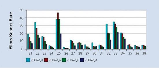
Figures 2 and 3. Pilot reports rate for ATA chapters 21–38 and 49–80.
Analysis of Reliability Monitoring by Manufacturer of One Aircraft Type
The air carrier will monitor the reliability of aircraft in operation and send the collected data to the aircraft manufacturer. Four times a year, on the basis of the collected data received from air carriers, the manufacturer issues a report on the reliability for a certain aircraft type available to all air carriers having that type of aircraft in their fleet. In the relevant report, collected and analysed data indicating reliability of aircraft components and system are presented. This is of great importance to the air carrier, since this can draw attention to an increased trend of failures of particular components, the untimely checking of which and, as needed, possible early service or replacement could cause non-airworthiness of aircraft due to technical malfunction. Each of the cases influences the safety of operations and represents high costs – hence, it is in the interest of the air carrier to prevent them.
The systematized and analysed results of one aircraft type manufacturer are presented below. The data presented are the result of monitoring the reliability of a fleet of 34 air carriers in one year, whose total flight hours amounted to 8 072 951 flight hours and 7 173 857 flight cycles.
In Figures 2 and 3 the pilot reports rates for certain ATA chapters are presented. The pilot reports are suspicions or confirmed malfunctions of aircraft components and system entered in a technical logbook and they demand inspection by technical staff. The pilot reports rate is calculated as the ratio of the number of pilot reports and the number of aircraft flight hours in a certain period, most often in a thousand hours of flight.
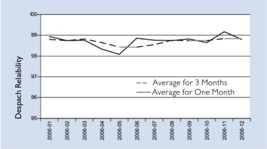
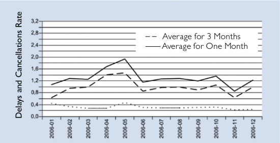
Despatch reliability is presented by graph in Figure 4, while Figure 5 presents the delay rate due to technical reasons and cancelled flights.
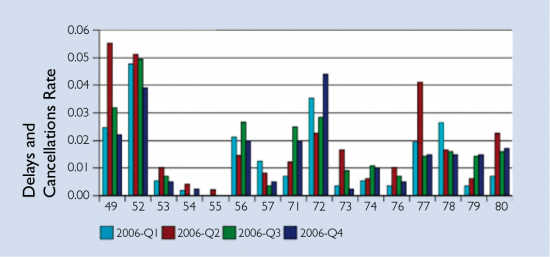
The delay and cancellations rate may also be classified by systems according to ATA specification, enabling the monitoring of components and systems most often failing, Figures 6 and 7.
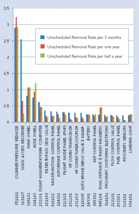
According to the results of monitoring, it is evident that aircraft components are the biggest cause of delay and cancellation. The reliability of particular components is presented in the report on reliability only if the component was registered as faulty. The histogram in Figure 8 presents 10 components which, after processing of all the data received, proved as being replaced most often.
Figure 4. Aircraft fleet despatch reliability.
Figure 5. Delays due to technical reasons and cancelled flights.
Figures 6 and 7. Delays and cancellations rate classified according to ATA chapters for 21–38 and 49–80.
Conclusion
A feedback on functionality, i.e. on the problems occurred during aircraft operation plays a big role and is of high importance in aircraft maintenance. Information that the air carrier can and must deliver to the aircraft manufacturer gives the manufacturer a possibility to collect and process data for a large number of aircraft seen as a fleet. On the basis of these data the manufacturer may identify the systems and/or components due to which problems in aircraft operation most often arise. If a defect in manufacture is established, modifications and installation of new components are introduced by the aircraft manufacturer, which should provide an increase of reliability in maintenance and operation. Also, an air carrier is obliged to deliver reports on reliability monitoring to aviation authorities as a proof that aircraft structure, power plant, its components and other systems are capable of achieving and maintaining reliability levels high enough, which is the basis for safety of carrying out aircraft operations.
Figure 8. Components with largest number of unscheduled removals.
»»References [1] Bazijanac, E.: Aircrafts Operation and Maintenance, Theoretical Fundamentals, Faculty of Transport and Traffic Sciences, Zagreb, 2007. [2] Airbus Customer Services: Reliability Control Program Training [3] Marušić, Ž.; Alfirević, I.; Pita, O.: Maintenance Reliability Program as Essential Prerequisite of Flight Safety, Traffic and Transportation, vol. XXI, No 4, 2009, pp. 269–277 [4] Marušić, Ž.; Alfirević, I.; Pita, O.: Methods of Increasing Reliability and Aircraft Maintenance System, Tehnički vjesnik, 14 No 3 i 4, 2007, pp. 37-45 [5] Žižić, Goran: Graduation thesis, Faculty of Transport and Traffic Sciences, Zagreb, 2010 (Mentor: Anita Domitrović) [6] Pažin, Ivana: Graduation thesis, Faculty of Transport and Traffic Sciences, Zagreb, (Mentor: Anita Domitrović) [7] Part M, European Aviation Safety Agency, http://www.easa. europa.eu/rulemaking/docs/ technical-publications/EASA_ Part-M.pdf, (May, 2011)






![EMR_AMS-Asset-Monitor-banner_300x600_MW[62]OCT EMR_AMS-Asset-Monitor-banner_300x600_MW[62]OCT](/var/ezwebin_site/storage/images/media/images/emr_ams-asset-monitor-banner_300x600_mw-62-oct/79406-1-eng-GB/EMR_AMS-Asset-Monitor-banner_300x600_MW-62-OCT.png)


