Low Cost On-Line Sensors for Condition Monitoring of Lubricating Oil
On-line sensors for monitoring lubricating oil machinery are now a reality. The main advantages of using of this kind of sensors are the access to lubrication conditions in extreme circumstances and not accessible machinery, the real knowledge of the mechanical components’ behavior in the machinery and the possibility to establish a good predictive and proactive maintenance to detect early stages of degradation of lubricating oil. These all benefits will lead to significant savings in maintenance and operational costs.
Industrial machinery suffers dramatic stops and failures because of undetected degradation and harmful contamination of lubricating oil. The monitoring of lubricant oil has traditionally been carried out by means of periodical oil sampling and laboratory analysis. However, it is not possible to detect and solve early stages of degradation through periodical analysis and very often the reaction time is too long which is the driver for on-line analysis [1, 2].
On-line sensors for the monitoring of lubricating oil in machinery are a reality today and can be a solution to many unsolved problems in the industry. The main advantage of using such sensors is real-time information of lubrication conditions also in extreme circumstances and in machinery that is difficult to access. Real-time information of the behaviour of mechanical components in the machinery, and the possibility to establish a good predictive and proactive maintenance strategy to detect early stages of degradation of the lubricating oil, are benefits which will lead to significant savings in maintenance and operational costs for the industry [3].
Furthermore the lubricating oil is usually changed at the discretion of the supplier, and this can be highly conservative; in a worst case scenario it is left so late that the degraded oil in the machinery can no longer ensure the proper functionality of the mechanical component. In addition environmental problems associated with lubricant wastes are reduced by reducing unnecessary oil changes.
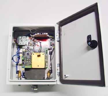
FIGURE 1. OilHealth® measurement module.
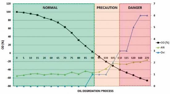
FIGURE 2. Degradation process of Mobilgear SHC XMP 320.
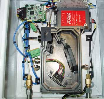
FIGURE 3. The final assembly of the different components of the Vis-NIR sensor.
OilHealth® Sensor
One of the most critical components in a wind turbine is the gearbox where monitoring of lubricant oil gives valuable information about the condition of the gearbox.
Because of the special operating conditions in offshore wind farms, the actual methodology is changing quickly towards intelligent systems integrated within the machine, which lowers the dependence of external laboratories.
The optical sensor is based on absorption spectroscopy, which correlates with the degradation stage of the lubricant oil. The system allows real-time and reliable measurement of oil from fresh to a fully-degraded condition; the sensor gives a percentage (Oil Degradation or OD (%)) value which indicates the remaining lifetime of the oil. By using this parameter it is possible to detect early stages of degradation or abnormal operation of the lubricating oil.
The sensor has been developed considering the extreme working conditions in the wind turbines and has been designed to eliminate the influence of bubbles or particles that could affect the measurements or pressure peaks and as a result, damage any component of the sensor. The sensor has been tested in pressures up to 10 bar and temperatures ranging from –20 to 70 ºC.
The validation has been carried out in the Wearcheck laboratory in test rigs and finally in actual environment in Wind turbines with the most important oils on the market – such as Shell Omala oil 320 (hd), Klüberoil Gem 1-320n, Klübersynth Gem 4-320n, Klübersynth GH 6- 320, Mobilgear SHC XMP 320, etc… – to ensure the robustness and reliability of the system.
The validation results show a very interesting correlation, not only in the final stages of degradation but during the entire degradation process. Complete oil degradation process results are shown in Figure 2 where the parameter OD (%) in the sensor signal. Acid Number and Oxidation levels do not detect any change until very late stages but the OD (%) starts changing from the initial degradation process allowing early planning of maintenance actions or tasks.
Visible-Near Infrared (Vis-NIR) Sensor
For many years lubricating oil conditions have not been properly monitored in marine diesel engines and in cogeneration gas engines. During its operating life cycle the lubricating oil is exposed to high pressures, temperatures and is contaminated with harmful external fluids and particles, which lead to the degradation of the oil.
The on-line Visible-Near Infrared sensor is a prototype that has been developed for condition monitoring of the main quality parameters of cogeneration gas engine and two stroke marine engine lubricating oils. The selected measurement range was 400–1100 nm so it covers the visible range (400–780 nm) and part of the short wave near infrared (780–1100 nm). With this sensor it is possible to monitor parameters such as Acid Number (AN), Base Number (BN), water content, viscosity and insoluble contents. Furthermore it is an environmentally friendly technology because it does not need oil sample chemical fitting up, i.e., solvents.
The design of the sensor provides an optical system, which splits the light in different wavelengths after it traverses an oil sample. These different wavelengths are gathered in the detector, which transforms the light signal into an electrical signal to obtain transmittance spectrums. The optical components used of the near infrared sensor are white light source, 150 μm pin-hole, spherical mirror to collimate the light towards the diffraction grating, a diffraction grating to separate the light source in different wavelengths and a second spherical mirror to collimate the light towards the 64 pixel array NIR detector operating in 400– 1100 nm range.
The mechanical design was developed to ensure the manufacturing availability and the main components are the optical components housing, the fluidic cell where the oil sample resides when the measurement is taken, the light source fixing and the detector fixing. The oil reaches the cell where the measurement is taken and the separation between the oil and the light system is done by means of two transparent windows in the Vis-NIR region of the light spectra.
The calibration of the sensor has been carried out by means of multivariate data analysis applying different chemometric methods and obtaining one predictive model for each parameter. The spectra obtained with the sensor has been correlated with the parameters analyzed in Wearcheck Iberica Oil Laboratory and the following steps have been applied in order to obtain the best calibration model for each parameter: data collection, data pre-processing and generation of a mathematical model and validation of the model.
The sensor has been tested with Cepsa 3040 Plus oil in SFGLD 560 model cogeneration engine at Guascor I+D facilities and with Castrol CDX 30 and BP Energol OE-HT 30 oil samples supplied by British Petroleum (BP) and obtained from two stroke marine engines. Table 1 shows the results obtained from the calibration models developed for the monitoring of gas engine lubricating oil. Regarding the work conditions of the sensor, it can support pressures up to 7 bars and temperatures equal to 100 ºC. [4, 5]
TABLE 1. The results obtained from the calibration models developed for the monitoring of gas engine lubricating oil.
FIGURE 4. Hardware of the Optical Particle Sensor.
FIGURE 5. Differences between the initial and final exposure time for the Castrol CDX 30 oil.
Optical Particle Detector (OPD)
The number and size of particles in lubricating oil are one of the most important indicators of failure type, type of wear and degree of wear in the machine.
The OPD sensor is a prototype that detects and quantifies the particles in the lubricating oil taking into account their size by taking a picture of the lubricating oil and identifying the size of the particles suspended into the oil. This process enables the artificial intelligence implemented into the sensor to classify the particles. A report is created with a picture of the oil with the particle detected in red and the number of particles ≥ 4 μm, ≥ 6 μm and 14 μm per ml of sample and the number of detected particles is extrapolated to ISO 4406 standard units. The sensor is connected to a PC by USB and the system powered by an external 220 V source.
As different oils have different light absorption coefficients, the sensor has an auto- calibration mode by means of adapting the exposure time of the camera to the absorbance of the oil that is being monitored. It is also possible to make the system perform a new calibration if the operator considers that it is needed (for example when the machine is already working but the oil to be monitored is changed).
At the end of the measurement cycle the report with the results is saved in the computer in two different formats. One as a .pdf file with the image and the detected particles pointed out and with the number of particles classified in three size categories and the other with data of the whole day’s detection history in Excel format (.xls).
The sensor has been tested with Castrol CDX 30 and BP Energol OE-HT 30 engine oil samples, with Mobil Jet Oil II aeronautic turbine oil and with the Skydrol hydraulic fluid used in aeronautic actuators. The tests have been carried out under pressures and temperatures up to 6 bars and 120 ºC.
Conclusions
New on-line sensors for machinery lubrication control are increasing the smart main tenance capabilities in many applications with difficult conditions for maintenance operations (from marine engines to wind farms). For instance, sensors presented here are able to monitor the main parameters of the lubricated machinery.
The goal for these sensors is not to have the same accuracy and precision as laboratory equipment, but to develop low cost on-line sensors with good enough accuracy and precision to determine the quality of the lubricating oil and help to decide if the oil change is necessary or not. As a result the costs and the environmental impact can be drastically reduced by preventing incorrect and unnecessary oil changes.
Atten2, Advanced Monitoring technologies, is a spin-off of the Technology Center Tekniker- IK4. The scope of work of Atten2 is the development, manufacturing and commercialization of online optical sensors for measuring specific characteristics of several fluids, and performing related services. This technology has been developed after years of successful R&D in the field of sensors and lubrication.
»»References ›› [1] Schalcosky, D.C., and Byington, C.S., (2000). Advances in Real Time O il Analysis. Practicing O il Analysis Magazine, 11, pp. 28–34. ›› [2] Gorritxategi, E., Arnaiz, E., Aranzabe, E., Aranzabe, A., Villar, A. (2009). O n-line sensors for condition monitoring of lubricating oil. Proceedings of 22nd International Congress on Condition Monitoring and Diagnostic Engineering Management COMADEM, San Sebastian, Spain, 2009, pp. 465–471. »»CSI 9420 Wireless V ibration Transmitter is now approved for ATEX Zone 0 and Class I, Div 1 areas. Emerson Process Management has expanded the application of its CSI 9420 Wireless V ibration Transmitter with intrinsic safety ratings to European, U S and Canadian standards. With ATEX Zone 0 and Class I, Div 1 ratings, the CSI 9420 can now be installed directly in hazardous areas such as chemical, petrochemical, and offshore facilities as well as other explosion-classified environments. The CSI 9420 connects quickly, easily and economically to any machine. The safety ratings, which are in addition to existing hazardous area ratings to the IECEx and B razilian standards, further extend the benefit of wireless technology to new areas of the plant. The CSI 9420 provides key insights into the condition of pumps, fans and other assets located in hazardous areas, without the expense of running cables.
A Heat Pump Plant Turns the Carbon Footprint of Textile Fibre Production Negative
Valmet launches intelligent fiber furnish control to secure better refiner operation
Valmet introduces the Valmet Fiber Furnish Control application package for board and papermakers to stabilize refiner operation for maximized production efficiency with ensured furnish quality. Based on real-time measurements of multiple fiber properties and freeness, the control features advanced feedback and feedforward solutions together with model predictive control.







![EMR_AMS-Asset-Monitor-banner_300x600_MW[62]OCT EMR_AMS-Asset-Monitor-banner_300x600_MW[62]OCT](/var/ezwebin_site/storage/images/media/images/emr_ams-asset-monitor-banner_300x600_mw-62-oct/79406-1-eng-GB/EMR_AMS-Asset-Monitor-banner_300x600_MW-62-OCT.png)
